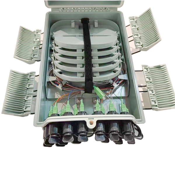
A typical fiber optic splice enclosure consists of several key components that work together to protect and organize the fiber splices. Standard enclosures contain: 1) Housing, 2) Cable fixation clamps, 3) Splice trays, 4) Sealing system. A splice box (also known as splice distributor) is a housing in which fiber optic cables begin or end. Fiber optics are fanned out in splice boxes that are situated at the end of fiber optic transmission paths. Optical cable joint box The optical cable joint box permanently connects two optical cables together and has a joint part for protecting components. The optical cable connection part, that is, the optical cable joint, is the part where the. An optical cable split fiber box, also known as a fiber distribution box or fiber optic splice closure, is a device used to terminate, splice, and distribute optical fibers. In this response, we will focus on the. This guide optimizes the original text by delving deeper into the three pillars of fiber network longevity: the impact of splicing technology, the strategic selection of splice boxes, and the essential maintenance protocols needed to ensure sustained, high-speed functionality. Fibre optic cables are manufactured in standardized lengths –.
[PDF]

Sensitivity Test: Confirms that the protection works properly for internal defects in the protected zone. Inject primary current via one set of CTs, with one current flowing inward & the other outward. If the CTs are properly connected, there should be no operating current at the. A protective relay is basically an electrical device that detects a fault in a power system and initiates the operation of the circuit breaker to isolate the defective section or component from the rest of the system. In other words, the prime function of protective relays is the timely and. To conduct the tests effectively the following devices and equipment are required: Primary Injection Test Kit – for injecting large currents directly into CT circuits. Secondary Injection Test Kit – Simulates relay inputs with the controlled currents and voltages. It emphasizes selectivity, coordination, fault response, and system behavior rather than individual relay devices. This prevents damage to equipment, reduces downtime, and safeguards. This handbook covers the code of practice in protection circuitry including standard lead and device numbers, mode of connections at terminal strips, colour codes in multicore cables, dos and donts in execution. Its main purpose is to safeguard electrical equipment like transformers, generators, and transmission lines from damage due to.
[PDF]

Multi-mode fiber optic patch cords utilize a larger core size, typically around 50-100 microns, allowing them to carry multiple modes of light. This design enables the transmission of data over relatively short distances with high bandwidth capabilities. A fiber-optic patch cord is a fiber-optic cable capped at each end with connectors that allow it to be rapidly and conveniently connected to telecommunication equipment. This is known as interconnect-style cabling. A fiber-optic patch cord is constructed from a core with a high refractive. These short fiber optic cords connect transceivers, switches, patch panels, and servers. Without them, even the best optical modules and switches cannot deliver performance. As data rates increase from 10G → 100G → 400G → 800G, patch cables must handle more bandwidth, more density, and stricter. Fiber optic patch cords, also known as fiber optic patch cables or fiber jumpers, are indispensable components in modern optical networks. They act as the critical link for interconnecting devices like optical switches, servers, and distribution frames. Understanding the various technical. Fiber patch cables, also called fiber-optic patch cords, are cables typically containing one or two optical fibers, which are equipped with standardized fiber connectors on both ends. The function of the fiber patch cord.
[PDF]

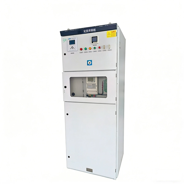
It connects to two independent power sources, enabling automatic switching to a secondary source during primary source failures. This seamless transition prevents disruptions to connected devices and enhances operational reliability. A dual power switching box is precisely the kind of gadget that guarantees a constant flow of electricity as it enables the user to shift the operational state between two different energy supplies. It can be found in homes, workplaces, factories, and anywhere else where sudden cuts of energy can. The ATS Dual Power Distribution Box plays a pivotal role in providing efficient low-voltage power solutions, ensuring that power flows seamlessly, even in the event of an outage. This comprehensive guide offers insights into the mechanisms and benefits of the ATS Dual Power Distribution Box. Transfer switches and sub panel boxes are key components in dual power switching cabinets. Transfer switches automatically switch between power sources during outages, ensuring uninterrupted power and system reliability. This redundancy ensures that if one power source fails, the other can immediately take over, minimizing downtime and preventing. A dual power switch helps you manage two power sources for one system. You can use it to keep your equipment working if the main power stops. This device quickly changes from the main supply to a backup source. This seamless transition.
[PDF]

This article describes the anti-pumping relay, its definition, function, and circuit diagram. In a circuit breaker it is desired that when close and trip operation is performed on the circuit breaker with the closing coil energized, the subsequent closing operation should be prevented. So let's. Anti-Pumping relay is nothing but a NO contact, which means when the circuit breaker in closed condition the relay will be as NO point and if the circuit breaker in open condition the relay will be as NC Condition. The anti-pumping relays is connected in series with the circuit. An anti pumping relay (also called antipumping relay or Y-relay and ANSI 94 Trip or Trip-Free Relay) is a protective device that prevents a circuit breaker from closing repeatedly when a continuous close command is present. In simple terms, it stops your circuit breaker from “pumping” – which means. Anti-pumping relays are used in circuit breakers to prevent the breaker from closing unexpectedly after tripping. If the TNC switch fails (Trip normal close) or there is any problem with the CB (circuit breakers) closing circuit, the continuous CB (circuit breakers) close command can be extended to. Why is the Anti-Pumping Relay Used? A circuit breaker is a very important equipment for a high-voltage power system. It protects the system from high current or voltage during a faulty condition.
[PDF]
This paper analyzes the basic principle and function of relay protection, summarizes the common fault types, and analyzes the fault analysis methods and treatment measures combined with actual cases. A method of fault tracking for relay protection devices is presented in this paper. Fault tracking means that after the failure of relay protection devices, the anomalies and warning informa-tion are obtained through data-mining technology, and then, the fault tracking algorithm is used. Relay fault diagnosis refers to the process of identifying and analyzing faults or abnormalities in protective relays. However, in actual operation, the relay protection device may cause failure due to hardware failure, software problems or external. For a long time, the fault diagnosis technology of relay protection consists of isolated cases and does not have a systematic method.
[PDF]

87N high-impedance protection requires special class × current transformer cores with equal transformation ratios. The 7SJ60 relay can alternatively be connected in series with the 7UT613 relay to save this CT core. Earth faults on the secondary side are detected by current relay 51N. However, it has to be time-graded against downstream feeder protection relays. Primary circuit-breaker and relay may be replaced by fuses. Go back to contents ↑. Relay 7UT612provides numerical ratio and vector group adaptation. Matching transformers as used with traditional relays are therefore no longer applicable. Line CTs are to be connected to separate stabilizing inputs of the differential relay 87T in order to ensure stability in the event of line through-fault currents. Relay 7UT613provides numerical ratio and vector group adaptation. Go back to contents ↑. The directional functions 67 and 67N do not apply for cases where the transformers are equipped with the transformer differential relays 87T. Go back to contents ↑.
[PDF]
The development of the relay protection based on open architecture is a relevant direction of electrical and electronic engineering. The paper presents the problem of the modern microprocessor-based relay prote.
[PDF]
In electric power systems and industrial automation, ANSI Device Numbers can be used to identify equipment and devices in a system such as relays, circuit breakers, or instruments. The device numbers are enumerated in ANSI/IEEE Standard C37.2 Standard for Electrical Power System Device Function Numbers, Acronyms, and Contact Designations. Many of these devices protect electrical. List of device numbers and acronyms• 1 - Master Element• 2 - Time-delay Starting or Closing Relay• 3 - Checking or Interlocking Relay, complete Sequence• 4 - Master Protective. A suffix letter or number may be used with the device number; for example, suffix N is used if the device is connected to a Neutral wire (example: 59N in a relay is used for protection against Neutral Displacement); and suffixe.
[PDF]
In fiber optic circuit technology an optical fiber link is used for transferring digital or analogue data in the form light frequency through a cable which has a highly reflective central core. Internally, the optical fiber.
[PDF]
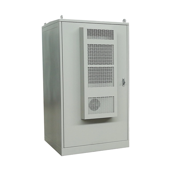
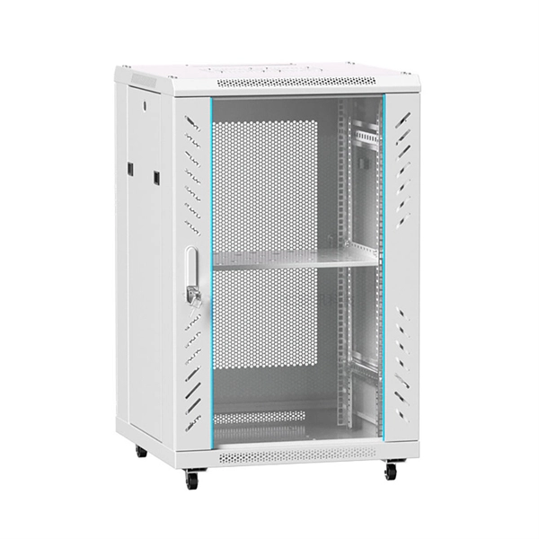
Through a real deployment case using E-abel server cabinets, we illustrate how cabinet design and connector architecture improve power reliability, reduce maintenance complexity, and support the increasing power density of modern data centers. Managing and installing a rack power distribution unit (PDU) has never been easier than with the EL2P PDU. Designed to simplify deployment and take stress out of power distribution, this intelligent PDU helps reclaim valuable hours. Whether that means speeding up Saturday installs or focusing on. An Intelligent Power Distribution Unit (iPDU), also known as a Smart PDU or Intelligent PDU, is a critical component in modern data center infrastructure. The units are available in horizontal 19-in. rack or vertical mounting capabilities. Why Has the Selection of Rack PDUs Become So Important?. For power distribution requirements of medium to large data centers, Delta's Power Distribution Unit (PDU) is an optimal solution. The space-saving PDU is easy to move and adapt to the future demands of the data center. The PDU offers superior power protection and monitoring, and the flexibility. Modern infrastructures typically rely on rack-level Power Distribution Units (PDUs), industrial CEE connectors, and structured cabinet designs to manage power connections efficiently. This article explores how power is connected inside modern data center racks, examining the flow of electricity.
[PDF]
The principle of gap-loss is used in optical attenuators to reduce the optical power level by inserting the device in the fiber path using an inline configuration. Gap-loss attenuators are used to prevent the saturation of the receiver and are placed close to the transmitter. The basic types of optical attenuators are fixed, step-wise variable, and continuously variable. The attenuator circuit will allow a known source of power to be reduced by a predetermined factor, which is usually expressed as decibels. In fiber systems, attenuation is specified in dB (a ratio), while optical power is often given in dBm (absolute power referenced to 1 mW). If a transmitter outputs +3 dBm and. If you are still looking to reduce the signal power of optical fiber links, Optical Attenuators are undoubtedly a good choice and can bring you a good solution. Because the signal power of the optical fiber link is too high, it will cause abnormalities in the optical fiber network, so it is. A Variable Optical Attenuator (VOA) is a controllable device used to reduce the optical power traveling through a fiber or free-space optical path. Unlike a fixed attenuator, which imposes a constant loss, a VOA allows the loss to be adjusted from nearly zero up to tens of decibels. Understanding their principles is essential for their effective application. Optical attenuators work by absorbing or reflecting a portion of the optical signal, thus reducing its.
[PDF]
Unlike a regular diode, the goal for a laser diode is to recombine all carriers in the I region, and produce light. Thus, laser diodes are fabricated using direct band-gap semiconductors.Component type, Working principle, Inventor, 1962; , 1962Pin names and Watch full videoOverviewA laser diode (LD, also injection laser diode or ILD or semiconductor laser or diode laser) is a device similar to a in which a diode pumped directly with electrical current can create. A laser diode is electrically a. The active region of the laser diode is in the intrinsic (I) region, and the carriers (electrons and holes) are pumped into that region from the N and P regions respectivel. Following theoretical treatments of M.G. Bernard, G. Duraffourg, and William P. Dumke in the early 1960s, light emission from a (GaAs) semiconductor diode (a laser diode) was demonstrat. The simple laser diode structure described above is inefficient. Such devices require so much power that they can only achieve pulsed operation without damage. Although historically important and easy to explain, such devic.
[PDF]
In fiber-optic communications, wavelength-division multiplexing (WDM) is a technology which multiplexes a number of optical carrier signals onto a single optical fiber by using different wavelengths (i., colors) of laser light. This guide delves into the principles, types, applications, and future trends of WDM. Tailored for professionals sourcing solutions from CommMesh, it. Abstract Wavelength division multiplexing or WDM allows the combining of a number of independent information-carrying wavelengths onto the same fiber, because of the wide spectral region in which optical signals can be transmitted efficiently. This chapter addresses the operating principles of WDM. Explore the fundamentals of Wavelength Division Multiplexing (WDM), its types, benefits, challenges, and future prospects in our detailed guide.
[PDF]
Thermal relays are the perfect solution for providing protection to motors which provides the most precise tripping for the electric motor during single phasing and overload. This article discusses an overview.
[PDF]