Over time, the constant expansion and contraction can make these cables brittle, increasing the risk of breakage, especially at joints and connectors. Ice accumulation is another significant concern in freezing weather. Fiber optic cables are the backbone of modern high-speed data transmission, offering unparalleled speed and reliability compared to traditional copper wires. Many advantages come with installing fiber optic cables over traditional copper cables, but that doesn't mean they are invincible. Fiber optic cabling problems with extreme cold happen when water finds its way into the ducts housing the cables. If water has the chance to enter into. Cold weather can affect fiber optic cables, but they are generally more resilient to temperature extremes compared to other types of cables, such as copper. Here's how cold weather can. For example, Bulgin's 4000 Series Fiber connector is the smallest sealed standard interface connector on the market. The fiber connection is UV resistant, salt spray resistant and sealed to IP66, IP68 and IP69K, while still providing an industry-standard LC interface as specified by IEC 61754-20. It's also widely utilized in telecommunications services, including the internet, television, and cellphones. Fiber optic internet connections are more popular globally because they provide various benefits over regular.
[PDF]

Shop DigiKey's large in-stock selection of Fiber Optic Attenuators. View inventory, pricing and order now for same day shipping!. Fiber optic attenuators are devices used to reduce or monitor the power level of a fiber optic signal. Basic types of fixed attenuation include single mode, dual window and multimode in D4/PC, FC, FC/UPC, MU, SC, SC/APC and UPC, ST and ST/UPC style connectors. Optical attenuators usually work by. FS fixed and variable fiber optic attenuators with leading attenuating fibers guarantee consistent and stable fiber attenuation (0~60dB) in WDM transmission. Thorlabs has a wide variety of single mode (SM), polarization-maintaining (PM), or multimode (MM) fixed and variable optical attenuators (VOAs). We offer SM and PM electronic VOAs that provide control of the output power with FC/PC or FC/APC connectors. Our SM and PM manual VOAs are available. Fibertronics, Inc. These attenuators are suitable for use in single mode 9/125, multimode 50/125, and multimode 62. This ensures optimal signal levels across fiber networks, preventing receiver overload and maintaining data integrity. These attenuators are essential. Attenuators are used to weaken or control a transmitted optical signal and preserve the quality of that signal when the laser or VCSEL is too strong for the receiver to read correctly. Attenuators are available in several styles and they can have either fixed levels of attenuation or they can be.
[PDF]

Optical Fiber Communication (OFC) revolutionizes modern telecommunications, enabling rapid data transfer across long distances with minimal signal loss. This comprehensive review explores OFC's historical evolution, core principles, components, and versatile applications. It traces OFC's. Additionally, optical fiber is lightweight and less susceptible to noise (no electromagnetic induction). Optical fiber consists of a cylindrical core that propagates light and a concentric cladding that surrounds it. The cladding's refractive index is slightly smaller than that of the core, which. Fibre optics and optical communications is the use of thin strands of glass for sending information encoded into light over long distances. Total internal reflection prevents light inserted into one end of the fibre from escaping through the sides. Keywords: Optical fibers, communication systems, data. Figure 1: Illustration of the inverse-square law of light intensity – the light's intensity diminishes with the square of the distance, which free-space optical signals must overcome (leading to very weak reception at long range) Figure 1 illustrates how light intensity decreases as distance.
[PDF]
Yes, single-mode fiber can transmit and receive data simultaneously. There are two ways to achieve this. We use wavelength division multiplexers (WDM Transceivers) to use this method. The single-mode optical fiber is designed and engineered to carry one single light mode in a minimal core diameter. This type of fiber is used for transmitting signals over long distances. It is specified as the best for especially long-distance applications than multimode fiber. Modes are the possible solutions of the Helmholtz equation for waves, which is obtained by combining. A single-mode fiber optic cable is an optical fiber designed to propagate light signals over long distances with minimal attenuation. It comprises one glass or plastic fiber and features a tiny core of about 8-10 microns in diameter. This small core permits only one light mode to propagate through. For a long time, fiber optic communication required two strands of fiber to accomplish full-duplex transmission—one strand for transmitting and the other for receiving. The core of the fiber is made of a highly transparent material, which allows the light to travel through it with minimal attenuation or loss of signal. This saves space and money. Dual fiber modules use two fibers.
[PDF]

To use a power meter for fiber optic testing, always clean connectors first with lint-free wipes or click-to-clean tools. Select the correct wavelength and set your reference. You measure optical power in dBm or insertion loss in dB. Consistent procedures ensure accuracy. Verify light travels from. The most basic fiber optic measurement is optical power from the end of a fiber. This measurement is the basis for loss measurements as well as the power from a source or presented at a receiver. Typically both transmitters and receivers have receptacles for fiber optic connectors, so measuring the. An optical power meter measures the strength of light traveling through a fiber optic cable, giving you a reading in dBm (decibels relative to one milliwatt). This article will guide you through the methods, instruments, and key considerations for measuring fiber. Fiber optic cabling is the high-performance core of today's datacom networks. As network speeds and bandwidth demands increase, fiber performance requirements have become more stringent. Fiber testing is more important than ever. An OPM uses a photodiode to generate an electrical current proportional to optical power.
[PDF]
Large-scale, densely distributed fiber Bragg grating (FBG) arrays have a wide range of applications in industrial safety surveillance. Due to the limitation of inscription pulse-width, most grating interrogator.
[PDF]

This practical file details experiments conducted in Optical Fiber Communication, covering modulation techniques, system components, and performance analysis. An optical fiber is a glass or plastic fiber designed to guide light along its length, widely used in fiber-optic communication, which permits transmission over longer distances and at higher data rates than other forms of communications. Fiber-optic communication is a method of transmitting. Availability of plastic optical fiber (POF) The plastic optical fiber used in some of these experiments is available for science distributors. It is a 1000micron (1mm) POF available from several suppliers. FOA has samples available at no cost for teachers at schools in the US. Key experiments include amplitude modulation, frequency modulation, and pulse width modulation, aimed at understanding fiber optic systems. This document summarizes 10 experiments on optical fiber communication: 1. Studying a 650mm fiber optic analog link and the relationship between input and received signals. Optical fiber communication Laboratory Optical fiber communication Laboratory List of Experiments: 1. To set up a analog optical fiber link 2. To measure the characteristics of LED and LASER 5. Tech curriculum designed to provide a comprehensive understanding of optical fiber communication systems. This lab offers an immersive, web-based simulator that enables you to explore and experiment with key concepts in optical.
[PDF]

Get answers to frequently asked questions about broadband services at BTC Bahamas. At Lightcommunication Company, we specialize in comprehensive fiber optic solutions, ensuring superior connectivity through expert services in installation, splicing, and network maintenance. We strive to revolutionize communication by providing cutting-edge fiber optic services that empower. BTC, also known as the Bahamas Telecommunications Company, is the national telecommunications company of the Bahamas. It offers a range of internet services, including fibre optic and DSL connections, and has a wide network of fibre optic cables, allowing it to provide high-speed internet to both. Clear Fiber Technology Solutions is a leading and reputable Telecommunications Contracting and Consulting Firm serving the Bahamas and Caribbean area. We understand the importance of Professional and Reliable Communications Services. We take a comprehensive approach to secure solutions, providing. Our aim is to provide reliable, cost effective, comprehensive solutions with efficient service to assist you in building I. infrastructure you can depend on. We want to be your partner of choice. call on us when you need to build out, upgrade or expand. Along the way we make it our mission to enrich lives and businesses through reliable, fast and future ready technology. Cable Bahamas nurtures education, wellness and cultural growth through dedicated partnerships and.
[PDF]
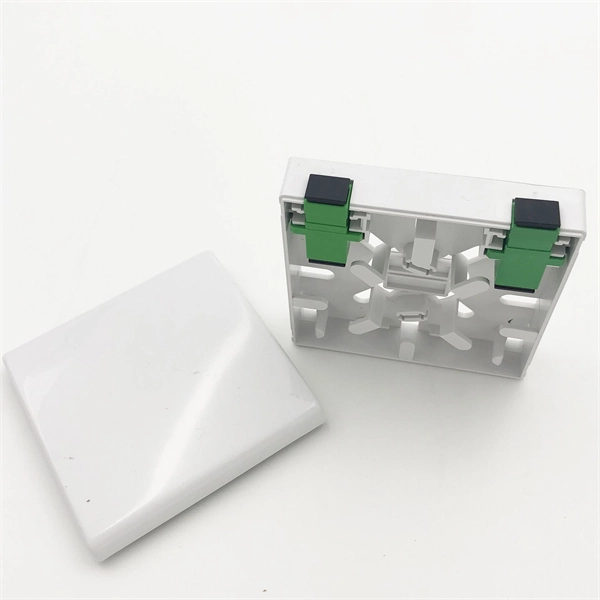
Feature -- 2 ports optical fiber distribution box is used for the fusion splicing, splitting, wiring transmission and other functions of the optical transmission terminal. It can effectively terminate, protect and manage the optical cable. It is a necessary equipment in network. Fibertech Misr supplies all components of fiber optic networks of fiber optic cable, patch cord, Pigtail, Adaptor, closure, Connector, media converter, over 11 years, the implementation of Telecommunications projects, Training for Welding, Measuring,FTTH,GPON, SDH,DWDM,CCTV,IP TV. Explore high-capacity Fiber Optic Patch Panels, Termination Boxes, and ODF solutions for robust telecommunications infrastructure. Our expertise, high-quality products, optimal cost/performance ratio, and time-saving approach set us apart from the competition. All Rights reserved. © 2026 COMTEC-SOL. COMtec Integrated Solutions, we are a leading manufacturer and vendor of cutting-edge Telecom infrastructure solutions, specializing in both Copper and Optical Fiber technologies. It's perfect for use in data centers and other telecommunications applications, and it's sure to provide you with the excellent performance that you need. Streamline your fiber connectivity with our premium Fiber Optic Patch Panels and ODF systems. Designed for reliability and ease of use, our rack-mount and wall-mount solutions provide the perfect environment for splicing, terminating, and managing your critical fiber optic connections.
[PDF]

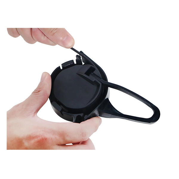
Different networks have different needs when it comes to fiber optic joint closures. At Multilink, we have a variety of closures to meet these needs, including inline types and drop terminals. In our selection, you can find the following termination. Different networks have different needs when it comes to fiber optic joint closures. At Multilink, we have a variety of closures to meet these needs, including inline types and drop terminals. In our selection, you can find the following termination enclosures and splice boxes for use with different cable sizes and numbers of drops: Optima™: The Op. The securing, storing and supporting of fiber optics and splices makes up an important step of fiber optic deployments in the field. Whether connecting to aerial or underground cables, telecommunications companies rely on fiber optic closures to protect and facilitate fiber splices and regular maintenance in Fiber to the Home (FFTH) and other indoo. With more than 35 years of experience, Multilink is a leader in the telecommunications industry. We make innovative products and help our customers succeed by providing high-quality equipment that's laboratory tested and proven to perform. Telecommunications companies often have unique requirements for their equipment. If you have a specific fiber.
[PDF]
In this guide, we'll walk you through the entire process of preparing fiber optic cable for splicing and termination to fiber connectors. We'll explore the necessary tools, safety precautions, and step-by-step procedures for cable connectors, mechanical and fusion. In this guide, you will find a chronological description of the fusion splicing process, the principal technical standards, and answers to the real-life questions network engineers and procurement teams may have. Therefore, we will also touch on cost factors, risk management, and best practices in. In this guide, we cover the basics of fiber optic splicing, how to perform splicing using two different methods, and finally some best practices to perform good fiber splicing. What is Fiber Optic Splicing and Why is it Needed? – #1. Two types of splices are used in fiber optic cabling one is Mechanical the other is Fusion. Before jumping into the physical steps, it's important to understand the two primary methods of fiber splicing: fusion splicing and. Learn how to splice fiber optic cable step by step in this complete guide! In this video, you'll see the full fiber splicing process — from fiber preparation, cleaving, and fusion splicing to final testing. For network managers and technicians, a poor splice can lead to significant signal degradation, network downtime, and costly troubleshooting.
[PDF]
In conclusion, choosing the right fiber optic connectors is an important decision that can have a significant impact on the performance and reliability of your fiber optic network. By considering the various factors.
[PDF]
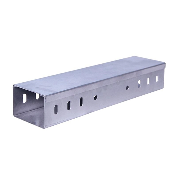
Optical cable tray is a system designed to protect and route fiber optic patch cords, cable assemblies to and from network cabinets, ODF and other terminal devices. Ducting offers ideal solutions for optical raceway requirements and application with pleasing appearance and easy. Our Fiber Cable Tray System is a comprehensive raceway solution for data center, enterprise, central office, and mobile switching center applications. Designed to route and protect fiber optic and high-performance copper cabling to and from network cabinets, distribution frames, and other terminal. Cable trays are a foundational part of this infrastructure, offering a secure, scalable, and organized method of managing fiber routing across diverse environments.
[PDF]
Glass fiber and plastic fiber is fragile. When individual fibers break, light transmission and uniformity are reduced. After the first few fibers break at a stress point, a chain reaction occurs, hastening t.
[PDF]

In this post, we'll walk you through practical tips, essential tools, common pitfalls, and the techniques that will help you get your fibre patch cable installations right the first time. Correct patch-cord installation is essential for maintaining low insertion loss, stable return loss, and long-term reliability in both indoor and outdoor fiber networks. Proper handling, routing, cleaning, bend-radius management, and connector alignment ensure that the optical link meets design. Proper connection of fiber optic cables is essential to harness these benefits fully, as even minor errors can lead to significant performance issues like signal loss. This guide addresses expert-certified best practices applied by professionals in the telecommunications, data. Yingda outlines the tools and materials needed to install fiber optic patch cords, as well as a complete step-by-step installation guide and important safety considerations to take. We will also tie this procedure back to the earlier discussion of multi-mode fiber types (OM1 to OM5) and connection. The Flex-Angle boot is designed to bend any angle or direction from straight to 90°. OMC flex angle boots for LC&SC fiber optic connectors are available on any single-mode or multimode patch cord. They are designed so the installer can pre-bend the boot into any direction or angle. Selecting the correct fibre patch lead is crucial for optimising signal performance and.
[PDF]