Due to power demands, there are currently no pluggable 10GBase-T or NBase-T SFP modules; all of the current products on the market are fixed interfaces only. 10GBase-SR is the original multimode optics specification and is still by far the most commonly used. A 10GB SFP module, more accurately referred to as a 10G SFP+ (Small Form-Factor Pluggable Plus) transceiver, is a hot-pluggable network interface module designed to transmit and receive data at speeds of up to 10 gigabits per second. It serves as the physical-layer connection between network. A broad range of industry-compliant SFP+ modules for 10 Gigabit Ethernet deployments in diverse networking environments. The Cisco ® 10GBASE SFP+ modules (Figure 1) give you a wide variety of 10 Gigabit Ethernet connectivity options for data center, enterprise wiring closet, and service provider. FS 10GbE SFP+ module solutions provide a wide variety of 10 Gigabit Ethernet connectivity options for data centers, enterprise wiring closets, Internet Service Providers (ISPs) applications. Click to get your 10G SFP+ transceiver modules from nearby warehouses. Trusted by 260K+. Single-fiber bidirectional (BIDI) optical modules must be used in pairs. For example, SFP-10G-BXD1 must be used with SFP-10G-BXU1. As it uses a single, low-cost. Our Cisco, HP and Brocade ready 10GBASE-SR Multimode SFP+ Modules feature low power consumption (<800mw) using Duplex LC OM3 fiber up to 300m (984').
[PDF]
The SFP-10G-ER transceiver module is the proven, standards-based workhorse for extending 10 Gigabit Ethernet up to 40km over cost-effective single-mode fiber. This hot-pluggable SFP+ transceiver is engineered to transmit 10Gbps data streams over single-mode fiber (SMF) for link lengths up to 40 kilometers, making it indispensable for metro Ethernet, campus backbone networks, enterprise data center interconnects (DCIs), and telecom access networks. 10GBASE-LR SFP+ Module: 10Gb/s data rate, Single-Mode, duplex LC connector, 1310nm wavelength, the transmission distance up to 10km, working temperature: 0℃ ~ 70℃, Tx Power (dBm): -6. Equipped with an LC connector. Experience reliable high-speed networking with the VIVOTEK SFP-2000-SM13-10, a 10 Gigabit Mini GBIC designed for enhanced performance. Utilizing 10GBase-X technology, it delivers data transfer speeds up to 10 Gbps over compatible cables, ensuring efficient and scalable connectivity. This module. The 10 Gigabit Singlemode SFP+ Transceivers provide high-performance, reliable connectivity for modern 10 Gigabit Ethernet (10GbE) networks. These transceivers are designed for singlemode fiber, offering superior performance over long distances. Whether you're working on data centers, campus. These SFP transceiver modules come in a metal housing that reduces electromagnetic interference and increases their durability.
[PDF]
Posi Fit™ box for use in Group I mining (low impact areas), Group II and Group III applications. High-temperature resistance, corrosion-resistant and anti-static properties. Raised domed lid facilitates connections to be made clear of the box base. Screw-on lid provides ease of. The ASEAN junction boxes market is a critical component of the region's broader electrical equipment and infrastructure ecosystem. Characterized by robust industrialization, rapid urbanization, and significant investments in energy and digital infrastructure, the market presents a dynamic landscape. Small Junction Box 10x15. 5cm Stainless Steel Junction Box, Hub for 4 Load Cells High Precision Potentiometer SUMMING Box 4 Way. Waterproof/Water Resistance case. Plus Included 4 Way Motherboard IP68 Waterproof Junction Box 4 Way/4 Pin Outdoor Connection Box, Cable Connector, Outdoor External. Open map of the world's electricity, telecoms, oil, and gas infrastructure, using data from OpenStreetMap. How can we improve? Choose from our selection of junction boxes, including over 2,800 products in a wide range of styles and sizes. Same and Next Day Delivery. Screw-on lid provides ease of installation. Lid. The world map below visualises the spread of the different plug types in use around the world. Red countries use type A & B plugs, the deep blue ones use types C & E / F (which are compatible with each other), yellow countries use type D, sea-green countries use the British type G plug, pink.
[PDF]
Fiber optic cable installation costs between $1,500 and $7,000 for your home, with prices varying by cable length and installation method. The installation type you choose and the layout of your property determine the total labor and materials needed for your project. How Much Does Fiber Optic Installation Cost Per Foot? Cable Material Costs: Installation Costs by Method: Prices can range from $1 to $50+ per linear foot depending on the method and complexity. The initial cost of installing fiber optic cables can vary depending on the chosen installation method. Home and business fiber optics projects typically range from a few hundred to several thousand dollars, depending on run length, fiber type, and labor needs. This. Whether you're running fiber to a home or a data center, here's exactly what contractors are charging in 2026. What is the real cost of fiber optic cable per foot in 2026? After analyzing 40+ U. fiber projects, we've assembled current material rates, labor burdens, and hidden fees. You should account for permit. If you're grappling with the complexities of budgeting for fiber optic installations 1, understanding the cost dynamics of single-mode fiber optic cables 2 is crucial. The price per foot includes the fiber itself, connectors, and basic installation factors, with main drivers being cable type, distance, and any required conduit or termination hardware. This article outlines cost expectations.
[PDF]
Comprehensive analysis of Burkina Faso's packaging import dynamics, emerging opportunities for regional suppliers, and how Grand-Chem is positioned to serve this strategic West African market. Learn about the market conditions, opportunities, regulations, and business conditions in burkina faso, prepared by at U. Embassies worldwide by Commerce Department, State Department and other U. agencies' professionals Distribution and sales channels are concentrated in the country's two. XRM lighting distribution box is a lightweight distribution device indispensable for secondary distribution in various industries. Can't find the product you need? Please give us feedback Address: No. Burkina Faso, landlocked in the heart of West Africa, represents one of the region's most promising.
[PDF]
The principle of gap-loss is used in optical attenuators to reduce the optical power level by inserting the device in the fiber path using an inline configuration. Gap-loss attenuators are used to prevent the saturation of the receiver and are placed close to the transmitter. The basic types of optical attenuators are fixed, step-wise variable, and continuously variable. The attenuator circuit will allow a known source of power to be reduced by a predetermined factor, which is usually expressed as decibels. In fiber systems, attenuation is specified in dB (a ratio), while optical power is often given in dBm (absolute power referenced to 1 mW). If a transmitter outputs +3 dBm and. If you are still looking to reduce the signal power of optical fiber links, Optical Attenuators are undoubtedly a good choice and can bring you a good solution. Because the signal power of the optical fiber link is too high, it will cause abnormalities in the optical fiber network, so it is. A Variable Optical Attenuator (VOA) is a controllable device used to reduce the optical power traveling through a fiber or free-space optical path. Unlike a fixed attenuator, which imposes a constant loss, a VOA allows the loss to be adjusted from nearly zero up to tens of decibels. Understanding their principles is essential for their effective application. Optical attenuators work by absorbing or reflecting a portion of the optical signal, thus reducing its.
[PDF]

Select the correct wavelength and set your reference. You measure optical power in dBm or insertion loss in dB. Consistent procedures ensure accuracy. Measure total signal loss from fiber, connectors, or splices. Optical fiber attenuation is the attenuation per unit length of optical fiber, and the unit is dB/km. When connecting two optical fibers, there will be loss inside any connector or joint. Consistent measurement techniques. While optical power meters are the primary power measurement instrument, optical loss test sets (OLTSs) and optical time domain reflectometers (OTDRs) also measure power in testing loss. TIA standard test FOTP-95 covers the measurement of optical power. Optical power is based on the heating power. Light Source: The CMA5 Series Light Sources provide an economical and stable laser source for use in point-to-point attenuation measurement. They feature a rugged design, built to withstand the difficult testing environment of fiber optic cable installation and maintenance. The CMA5 Light Sources. When talking about optical measurements, wavelength basically means how far a wave pattern repeats itself, usually measured in nanometers (nm). Commonly, a power meter on its own is used to measure absolute.
[PDF]

Shop network switches, including PoE, managed, unmanaged, and gigabit switches. Get high-performance connectivity with easy setup, competitive prices, and express delivery. An LPO (Linear Pluggable Optics) solution offers considerable power savings for optical interconnect by removing the digital signal processing (DSP) function from the pluggable optical module. This architecture takes advantage of the capabilities in each segment of the link to form a power, cost. One of the most groundbreaking network innovations driving transformations of data centers in 2025 is Linear Pluggable Optics (LPO)—a Digital Signal Processor (DSP)-free optical solution designed to optimize power, cost, and latency. At Dell Technologies, we are excited to offer fully supported. Upgrade your network with top-of-the-line switches. a wide array of high-performance network switches designed to enhance data transfer, improve efficiency, and ensure seamless connectivity. Linear Pluggable Optics (LPO) has emerged as a promising solution to address this challenge, offering a more efficient way to move data within server racks. Unlike its predecessor, Co-Packaged Optics (CPO), which integrates optical components directly into the electrical package, LPO focuses on. Simple and flexible solutions ideal for IoT deployments and out-of-the-wiring-closet setups. Operates on Cisco IOS Software, offering CLI and web UI for easy device and network management. Fast delivery across.
[PDF]

We have identified 63 global optical fibre cable tenders from the public procurement domain worldwide. View the latest global tenders for optical fibre cable from Africa, the Americas, Asia, Australia, Europe, the Middle East, and other countries. Recently, China Mobile's centralized procurement results of ordinary optical cables from 2021 to 2022 have been released. 2 million core kilometers). Compared. Find RFP searches and finds fiber optics bids, contracts, and request for proposals. Below is a sample search result showing the newly published government contracts and bids in fiber optics, cabling, wiring. These include government RFPs, RFTs, RFIs, RFQs in fiber optics from federal, state, and. China Mobile released details regarding the awards of their 2025/2026 loose-tube optical cable tender on 7 June 2025 – less than one month after announcing the tender on 8 May 2025. As anticipated, competition for the 98. 8M F-km optical cable tender was intense. 654E optical fiber and cable product centralized procurement project have been implemented, and the procurement conditions have been met, and now public. The Bid For China Mobile Ordinary Optical Cables Central Procurement (2021-2022) Of 9 Billion Yuan Won By YOFC And Other 14 Companies Today, China Mobile announced the results of centralized procurement of ordinary optical cable products from 2021 to 2022.
[PDF]

The BA-1 device produces step attenuation of a laser beam to a maximum of about 44 dB . With the preattenuator beam splitter, denoted by SI, this range can be extended as much as another 3 0 dB. The various low level beams generated by BA-1 can be used for detector respon-sivity and. Danielson, B. (1977), Measurement procedures for the optical beam splitter attenuation device BA-1:,, National Institute of Standards and Technology, Gaithersburg, MD, , https://doi. 77-858 (Accessed February 10, 2025) If you have any questions about this publication or. Beam splitters are optical devices that play a crucial role in various scientific and industrial applications. They are used to divide a beam of light into two or more separate beams. NBS interagency report is a publication of the U. The papers are in the public domain and are not subject to copyright in the United States. The BA-1 system is designed for use at. The attenuation ratios of these wavelengths are calculated values. An analysis of the estimated uncertainties is. SPLITTER ATTENUATION DEVICE BA-1 B. Danielson Measurer::ent procedures are described for the step attenuation of laser bearriS up to 44 dB using a specially constructed attenua- tor box (BA-1). a laser beam) into two (or sometimes more) beams, which may or may not have the same optical power (radiant flux).
[PDF]

An Optical Splitter, also known as a beam splitter, is a passive optical device that divides a single input optical signal into two or more output signals. Conversely, it can also combine multiple signals into one. Knowing the difference between a splitter and an optical coupler helps you build better networks. You make your network work better when you pick the right device for each job. You can connect many users to one port with 1:n or 2:n splitters. By dividing a single optical signal from a central Optical Line Terminal (OLT) into multiple outputs for Optical Network Terminals (ONTs) at users' homes, splitters eliminate the need for dedicated fibers to each residence—slashing infrastructure costs while scaling network reach. This guide. In a Passive Optical Network (PON), a single optical fiber carries massive amounts of data using light. Signal Input: The fiber splitter receives the optical signal from the upstream network node and enters the splitter through the input fiber. Signal Distribution: Inside the splitter, according to the design structure and different. Splitters are passive optical devices that divide or combine optical signals, and they come in various types, including power splitters, uneven splitters, and wavelength-division multiplexing (WDM) splitters. Each type serves specific applications, enabling efficient use of optical infrastructure.
[PDF]

This report covers the optical, environmental, and mechanical performance of the LC-UPC, singlemode fiber optic BOAs, provided by Tyco Electronics, Fiber Optics Business Unit. Qualification testing was completed by a third party in July 2004. IDEAL FOR DEBUGGING OPTICAL POWER PERFORMANCE & OPTICAL INSTRUMENT CALIBRATION CORRECION & FIBER SIGNAL ATTENUATION. As optical passive devices, FS attenuators are mainly used in fiber optic to debug optical power performance & optical instrument calibration correction & fiber signal. L-com offers an extensive line of dual wavelength (1310/1550nm) Singlemode fiber optic attenuators. These versatile in-line attenuators are the perfect solution for attenuating Singlemode fiber connectors for both lab and commercial applications. Constructed of the highest quality materials and. zation system's perfo. the power of an optical signal. Our LC/APC single mode attenuators can handle a maximum o 1 watt of optical input power. This device contains one ale and one female LC/APC port. LC/APC optical attenuators can be ordered in attenuation. Fixed loopback type attenuators from OMC offer defined control of optical signals in both integrated and add-on products. Depending on the project or need, fixed attenuators can limit (attenuate) the amount of light passing through to the exact levels your project or application requirement.
[PDF]

Wavelength: 1310nm, 1550nm, or CWDM/DWDM wavelengths. LR (Long Range): 10km, 1310nm, Blue latch. Each SFP module operates at a specific wavelength, and to avoid confusion, manufacturers use color-coded pull rings for easy identification. Here's a quick guide: 🔹 850nm (Black) – Short-distance multimode fiber (up to 550m) 🔹 1310nm (Blue) – Longer reach, typically used for single-mode fiber (up. Wavelength division multiplexing modules differ from other optical modules in center wavelengths. Wavelength division. Coarse Wavelength Division Multiplexing (CWDM) SFP modules are a practical and cost-effective solution for expanding network capacity while keeping equipment simple and scalable. Selecting the right wavelength for CWDM SFPs is essential to ensure optimal performance, minimal interference, and. Every optical transceiver operates at a specific wavelength, typically measured in nanometers (nm). Their pull. SFP (Small Form-factor Pluggable) is a compact, hot-swappable module used in network devices such as switches, routers, and servers to provide network connectivity and is widely used in network communications. Think of it as the “translator” for your network equipment, converting electrical signals into optical signals.
[PDF]

Uses 12 wavelengths derived by shifting 6 traditional CWDM wavelengths left and right (±3. 5nm) using temperature tuning. Balances cost and channel density. Applications: Primarily 5G mobile fronthaul and midhaul networks requiring moderate capacity and cost efficiency. In fiber-optic communications, wavelength-division multiplexing (WDM) is a technology which multiplexes a number of optical carrier signals onto a single optical fiber by using different wavelengths (i., colors) of laser light. This technique enables bidirectional communications over a. This is the complete guide to Dense Wavelength-Division Multiplexing (DWDM) wavelengths and channels in 2024. Then, you will enjoy this new complete DWDM wavelength channels guide. What are the benefits of DWDM? #3. DWDM and CWDM enable carriers to deliver more services over their existing fiber infrastructure by combining multiple wavelengths on a single fiber. But navigating the alphabet soup of CWDM, DWDM, MWDM, LWDM, and SWDM can be daunting. 5 nm (800 GHz) in the O-band of 1270–1330 nm by using x-cut lithium-niobate-on-insulator (LNOI) photonic waveguides for the first time.
[PDF]

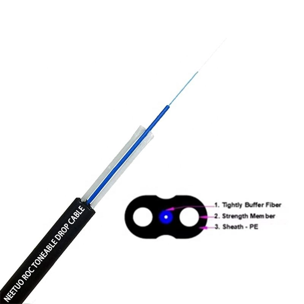
Since the earliest days of fiber optics, multimode cables have typically been color‑coded orange, black, or gray, while single‑mode cables are marked in yellow. For example, cable jacket color typically defines the fiber type, and can differ based on mode and performance level. These colors are typically chosen by industry standards bodies. However, there are some non-standardized colors and inconsistencies that you should be aware of. However, with the introduction of metallic connectors like FC and ST—whose bodies are difficult to color‑code—colored strain relief boots. Multimode fiber (MMF) is a kind of optical fiber mostly used in communication over short distances, for example, inside a building or for the campus. Multimode fiber optic cable has a larger core, typically 50 or 62. 5 microns that enables multiple light modes to be propagated. Because of this, more. Originally developed by the Electronic Industries Alliance (EIA) and the Telecommunications Industry Association (TIA), the TIA-598-D standard (formerly EIA/TIA-598) remains the most recognized color-coding system for optical fibers worldwide. On the right, the yellow patchcord indicates singlemode fiber and the blue connector means it is a regular PC polished connector, If it were an APC connector, it would be green. Perhaps nothing is.
[PDF]