MTF-01 is an optical flow ranging integrated sensor developed by MicoAir Technology. It uses uart to output data and is compatible with mainstream open source flight controllers such as Ardupilot, PX4 and INAV. It can be used directly after simple configuration without complicated. The micolink is a lightweight protocol customized by MicoAir Tech, prepared for developers who are ready to write their own code to read sensor data. MicoAssitant software can used for configure protocol or other parameter of MTF-01. Step1 : Connect the MTF-01 to PC by using the USB to TTL module. The is a lightweight 2 in 1 optical flow sensor including a short range lidar which uses the serial MAVLink protocol to communicate with the autopilot. This can be used to improve horizontal position control especially in GPS denied or indoor environments. Users can switch communication protocols through the USB to UART TTL module, adapting to different flight control systems. Easy to Operate:. MTF-01 and MTF-01P use more powerful TOF sensors, providing a longer range. The MTF-01P also utilizes a laser light source, extending the maximum range to 12 meters, and includes an injection-molded casing. Featuring the MTF-01 module, it delivers precise optical flow data, enhancing drone stability and maneuverability. With the PMW3901 sensor, it provides accurate 8-meter laser ranging.
[PDF]

This article provides a detailed technical comparison between fiber optic and copper cables, offering a clear perspective for engineers, network architects, and procurement managers. The core distinction between the two technologies lies in the physics of data. There are significant differences in performance between ADSS cables (all-dielectric self-supporting optical cables) and traditional optical cables, which are mainly reflected in the following aspects: 1. This type of fiber optic cable is designed to support its own weight without the need for additional support structures like messenger wires. The ADSS. There are several factors to assess when deciding which cable type is right for your application, including speed of connection for new customers, ease of changes and repairs, installer certification requirements, and the ability to expand the network over time. ADSS Fiber Optic Cables are a type of optical fiber cable designed specifically for. All-dielectric self-supporting (ADSS) cable is a type of optical fiber cable that is strong enough to support itself between structures without using conductive metal elements. It is used by electrical utility companies as a communications medium, installed along existing overhead transmission.
[PDF]

Per‑unit estimates often appear as $0. 50 per ft for basic fiber plus additional charges for trenching and install labor. Several drivers shape fiber installation pricing. Homeowners and businesses typically pay for fiber optic cable installation based on distance, conduit needs, and labor. The main cost drivers include material type, run length, trenching or aerial work, and any required permits or inspections. This guide provides clear cost estimates, price ranges. The initial cost of installing fiber optic cables can vary depending on the chosen installation method and specific project requirements. Total Project Costs: For commercial installations, expect costs ranging from $5,000 to $20,000 per mile for underground projects and from $40,000 to $60,000 per. Buyers typically pay for fiber laying by combining material costs, labor time, and permitting plus trenching or aerial support fees. A short residential drop under 1,000 ft may cost $3,000-$8,000, while longer runs to an attached garage or street node can run $8,000-$25,000. The price often reflects project scope, geography, and local regulations, making. Fiber optic cable costs vary widely – from $0. Installation can be more expensive than the cable itself, especially with site challenges.
[PDF]

An Optical Splitter, also known as a beam splitter, is a passive optical device that divides a single input optical signal into two or more output signals. Conversely, it can also combine multiple signals into one. Knowing the difference between a splitter and an optical coupler helps you build better networks. You make your network work better when you pick the right device for each job. You can connect many users to one port with 1:n or 2:n splitters. By dividing a single optical signal from a central Optical Line Terminal (OLT) into multiple outputs for Optical Network Terminals (ONTs) at users' homes, splitters eliminate the need for dedicated fibers to each residence—slashing infrastructure costs while scaling network reach. This guide. In a Passive Optical Network (PON), a single optical fiber carries massive amounts of data using light. Signal Input: The fiber splitter receives the optical signal from the upstream network node and enters the splitter through the input fiber. Signal Distribution: Inside the splitter, according to the design structure and different. Splitters are passive optical devices that divide or combine optical signals, and they come in various types, including power splitters, uneven splitters, and wavelength-division multiplexing (WDM) splitters. Each type serves specific applications, enabling efficient use of optical infrastructure.
[PDF]

Run the display transceiver [ interface interface-type interface-number | slot slot-id ] [ verbose ] command to view information about the optical module on a specified interface. In optical communication equipment, an optical module (Optical Module) contains several types of semiconductor chips that work together to complete the transmission and processing of optical signals. These chips typically include laser chips, photodetector chips, driver chips, transimpedance. When the optical module on an interface is faulty, you can run the display commands to view information about the optical module. Today, we will deeply analyze the four mainstream models of 100G QSFP28 dual-fiber optical modules: QSFP28-100G-SR4, QSFP28-100G-LR4, QSFP28-100G-ER4 and. The following uses the Moduletek SFP-10G-LR module connected to a Huawei S6700 switch as an example to introduce how to read information of the connected optical module on a Huawei switch. Figure 1 Schematic Diagram of Optical Module Connected to Switch 1. Optical Module Status Check Run the. Upgrade to 100G or 400G optics and save. Cisco Transceiver Modules - Learn product details such as features and benefits, as well as hardware and software specifications. Network administrators have a major challenge determining the right Cisco SFP modules, understanding complex model numbers that directly affect network performance and stability.
[PDF]

This report covers the optical, environmental, and mechanical performance of the LC-UPC, singlemode fiber optic BOAs, provided by Tyco Electronics, Fiber Optics Business Unit. Qualification testing was completed by a third party in July 2004. IDEAL FOR DEBUGGING OPTICAL POWER PERFORMANCE & OPTICAL INSTRUMENT CALIBRATION CORRECION & FIBER SIGNAL ATTENUATION. As optical passive devices, FS attenuators are mainly used in fiber optic to debug optical power performance & optical instrument calibration correction & fiber signal. L-com offers an extensive line of dual wavelength (1310/1550nm) Singlemode fiber optic attenuators. These versatile in-line attenuators are the perfect solution for attenuating Singlemode fiber connectors for both lab and commercial applications. Constructed of the highest quality materials and. zation system's perfo. the power of an optical signal. Our LC/APC single mode attenuators can handle a maximum o 1 watt of optical input power. This device contains one ale and one female LC/APC port. LC/APC optical attenuators can be ordered in attenuation. Fixed loopback type attenuators from OMC offer defined control of optical signals in both integrated and add-on products. Depending on the project or need, fixed attenuators can limit (attenuate) the amount of light passing through to the exact levels your project or application requirement.
[PDF]

Explore 74 top manufacturers and suppliers of Optical Testing Instruments in our comprehensive photonics buyers' guide. An optical testing instrument is a device or system used to evaluate and measure the performance, quality, and characteristics of optical components. Source Photonics, founded in 1988 and based in Los Angeles, California, is a technology company that specializes in optical transceivers and data connectivity solutions. The company provides a wide range of products tailored for data centers, broadband, and optical transmission, serving. CACI designs and manufactures optical communications terminals for all of the major orbits in which our customer missions operate. These bespoke solutions are being manufactured in Orlando at CACI's space manufacturing and testing facility, which opened in June 2022. The facility is dedicated to. Manufacturer of standard and custom opticaltestequipment including microscopes, pocket comparators, disc gages, grids, scales, strips, slits, and micrometers. Suitable for optical, gaging, imaging, and calibration applications. Serves aviation industry. Lapmaster Wolters is estimated to have. Optical transceivers are devices that convert electrical signals into optical signals for transmission and reception. They are primarily used in communication systems that employ optical fiber cables, serving the purpose of signal conversion between the transmitting and receiving ends.
[PDF]

Wavelength: 1310nm, 1550nm, or CWDM/DWDM wavelengths. LR (Long Range): 10km, 1310nm, Blue latch. Each SFP module operates at a specific wavelength, and to avoid confusion, manufacturers use color-coded pull rings for easy identification. Here's a quick guide: 🔹 850nm (Black) – Short-distance multimode fiber (up to 550m) 🔹 1310nm (Blue) – Longer reach, typically used for single-mode fiber (up. Wavelength division multiplexing modules differ from other optical modules in center wavelengths. Wavelength division. Coarse Wavelength Division Multiplexing (CWDM) SFP modules are a practical and cost-effective solution for expanding network capacity while keeping equipment simple and scalable. Selecting the right wavelength for CWDM SFPs is essential to ensure optimal performance, minimal interference, and. Every optical transceiver operates at a specific wavelength, typically measured in nanometers (nm). Their pull. SFP (Small Form-factor Pluggable) is a compact, hot-swappable module used in network devices such as switches, routers, and servers to provide network connectivity and is widely used in network communications. Think of it as the “translator” for your network equipment, converting electrical signals into optical signals.
[PDF]

The optical module is usually composed of Transmitter Optical Subassembly (TOSA, containing a laser LD Chip), Receiver Optical Subassembly (ROSA, containing a photodetector PD Chip), a driving circuit, and an optical and electrical interface. Its schematic is shown in. This section explains the structure of a typical pigtail butterfly module, which gets its name from the two rows of seven leads at right angles on each side of the metal package plus an optical fiber pigtail at one end (Fig. Let's look at the internal structure (Fig. 2) of a common butterfly. Optical modules are devices used to connect network devices, transmit and receive data between network devices, and can be used to convert optical and electrical signals. The optical module is a very important component in an optical communication system. Optical devices are the core components of optical modules. TOSA and ROSA in Common Optical Transceiver Modules For ordinary optical transceiver modules, there are two optical devices, TOSA and ROSA, which have opposite effects.
[PDF]

However, there are still some scenarios where an optical drive is necessary or desirable. What is an Optical Drive?. THe Optical memory is an electronic storage medium that uses a laser beam to store and retrieve digital (binary) data. In optical storage technology, a laser beam encodes digital data on an optical disc or laser disc in the form of tiny pits arranged in a spiral pattern on the surface of the disc. In this article, we'll explore the pros and cons of having an optical drive and help you decide whether you need one. Although a number of optical formats have been used over time, the most common examples are optical discs such as the compact disc (CD) and the digital versatile disc (DVD). The primary components of an optical drive include a laser, a lens system, a motor for spinning the disc, and a decoder to interpret the data. It is commonly found in computers, laptops, and gaming consoles. Optical drives are essential for installing software, playing movies, and backing up data.
[PDF]

NPO (Near-Packaged Optics) is a transitional technology bridging traditional pluggable modules and CPO. It integrates the optical engine and GPU chip side-by-side on the same high-performance PCB or organic substrate, connected via ultra-short high-speed circuits. Its core concept is to remove digital processing units such as DSPs and CDRs from the module, constructing a purely analog "linear direct-drive" optical link. In the LPO architecture: The transmitter uses a high-linearity driver chip to directly drive the optical modulator, converting the. Near-packaged optics (NPO) helps send data faster. It puts the optical engine close to the switching chip. This makes things work better. NPO lets you upgrade easily. You do not have to redesign your whole system. It lowers energy costs. Among the emerging technologies, LPO (Linear Pluggable Optics), NPO (Near-Packaged Optics), and CPO (Co-Packaged Optics) represent three important stages in the evolution of next-generation data center optical networking. Understanding how these architectures differ is essential for designing. Traditional optical modules typically rely on DSPs (Digital Signal Processors) to handle signal equalization, retiming, and compensation, mitigating attenuation and distortion during transmission. They are not concepts at the same level, but rather.
[PDF]

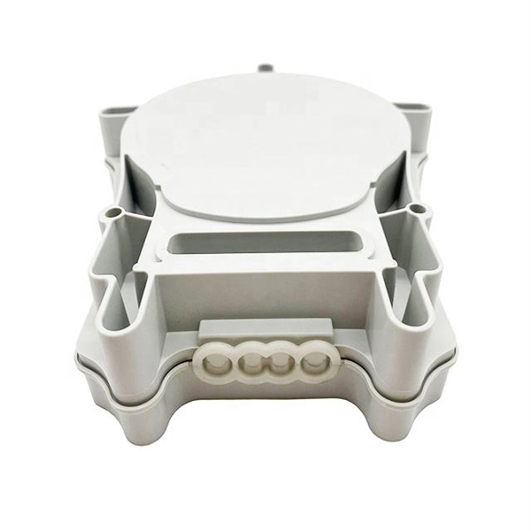
Here's a step-by-step guide to help you set up your fiber distribution box seamlessly: Before installing the fiber distribution box, ensure that your optical cables are properly prepared for connection. The optical fiber distribution box allows people to easily access the optical fibers in the box, and can well protect the optical fibers. In addition, the drawer structure also facilitates high-density wiring and good cable management. However, because optical fibers are fragile and can be easily. Keeping this page as a placeholder for now. Have any questions? Talk with us directly using LiveChat. Fix the rack to the ground with expansion bolts. Top installation: Dimensions of four connection holes on the top according to the. This instruction describes the installation of the Fiber Distribution Frame (FDF) manufactured by Corning Optical Communications. To order accessories that are purchased separately, contact Corning Optical Communications customer care for assistance. Read and understand this procedure (as well as. Optical fiber distribution frame is the wiring connection equipment between optical cable and optical communication equipment or between optical communication equipment. Distribution boxes are especially essential for FTTH networks, where they enable the efficient connection and management of optical fibers from a central.
[PDF]

Optical Fiber Communication (OFC) revolutionizes modern telecommunications, enabling rapid data transfer across long distances with minimal signal loss. This comprehensive review explores OFC's historical evolution, core principles, components, and versatile applications. It traces OFC's. Additionally, optical fiber is lightweight and less susceptible to noise (no electromagnetic induction). Optical fiber consists of a cylindrical core that propagates light and a concentric cladding that surrounds it. The cladding's refractive index is slightly smaller than that of the core, which. Fibre optics and optical communications is the use of thin strands of glass for sending information encoded into light over long distances. Total internal reflection prevents light inserted into one end of the fibre from escaping through the sides. Keywords: Optical fibers, communication systems, data. Figure 1: Illustration of the inverse-square law of light intensity – the light's intensity diminishes with the square of the distance, which free-space optical signals must overcome (leading to very weak reception at long range) Figure 1 illustrates how light intensity decreases as distance.
[PDF]
An optical time-domain reflectometer (OTDR) is an optoelectronic instrument used to characterize an optical fiber. It is the optical equivalent of an electronic time domain reflectometer which measures the impedance of the cable or transmission line under test. An OTDR injects a series of optical pulses into the fiber under test and extracts, from the same end of the fiber, light that is scatter. Reliability and quality of OTDR equipmentThe reliability and quality of an OTDR is based on its accuracy, measurement range, ability to resolve and. The common types of OTDR-like test equipment are: 1. Full-feature OTDR: 2. Hand-held OTDR and Fiber break locator: 3. RTU in RFTSs:. In the late 1990s, OTDR industry representatives and the OTDR user community developed a unique data format to store and analyze OTDR fiber data. This data was based on the specifications in GR-196, G.
[PDF]

Highly compact electro-optical modulators have been demonstrated in compound semiconductors. However, in silicon photonics, electro-optical modulation has been demonstrated only in large structures, and is therefore inappropriate for effective on-chip integration.OverviewAn is an optical device which is used to modulate a beam of light with a perturbation device. It is. An electro-optic modulator is a device which can be used for controlling the power, phase or polarization of a laser beam with an electrical control signal. It typically contains one or two, and possibl. Acousto-optic modulators are used to vary and control laser beam intensity. A Bragg configuration gives a single first order output beam, whose intensity is directly linked to the power of RF control signal. The rise ti. A dc magnetic field Hdc is applied perpendicular to the light propagation direction to produce a single domain, transverse directed 4~Ms. The rf modulation field Hrf, applied by means of a coil along t.
[PDF]
