
A FOSC is a protective enclosure designed to house, organize, and environmentally seal optical fiber splices, providing mechanical protection, water resistance, and easy re-entry for maintenance. At the core of this system's precision and reliability are Fiber Optic Splice Boxes—the unsung heroes that house and protect the delicate junctions where fiber cables are joined. The integrity of these enclosures is paramount to network performance. This guide optimizes the original text by delving. A splice box (also known as splice distributor) is a housing in which fiber optic cables begin or end. The main components of a splice box are the splice cassette that picks up the fibers and. Optical cable joint box The optical cable joint box permanently connects two optical cables together and has a joint part for protecting components. The optical cable connection part, that is, the optical cable joint, is the part that protects the connection between two or more optical cables by the optical cable. In the fast-evolving world of fiber optic networks, where FTTH connections surpass 2 billion globally and 5G/50G-PON deployments accelerate, one component quietly ensures long-term reliability: the Fiber Optic Splice Closure, commonly abbreviated as FOSC. Optical cable splice boxes protect the splicing parts of optical fibers from various hazards, such as water seepage due to adverse.
[PDF]
An improper cleaving angle can lead to uneven fibre surfaces, which makes it difficult for the fusion splicer to align the fibres. The cleaver should produce a perpendicular cut to the fibre to ensure proper alignment during splicing. Poor cleaving is one of the most common causes of poor splice results when using a fusion splicer. When cleaving isn't done correctly, it can lead to gaps, misalignment, or even an incomplete splice, which can compromise the integrity of your network. But fear not; there are simple troubleshooting. The performance of a fiber optic splice is determined by a number of factors, including the quality of the fiber, the cleanliness of the splice, and the techniques used to make the splice. Intrinsic factors, such as the refractive index of the fiber, are those that are inherent to the fiber itself. To counteract these errors, technicians can go through the following troubleshooting checklists: Perform an Arc Test: Before splicing, it's important to perform. One of the most frequent complaints among technicians is unexpectedly high splice loss. The root causes typically include: To resolve this, first. The fiber diameter appears reduced where the two fibers were joined. A “too thin” splice is typically caused by excessive stretching of the molten glass during the arc.
[PDF]

Mechanical splicing is a fast way to join two fiber optic cables. Instead, you line up the fibers inside a small holder made of plastic or metal. The holder keeps the fibers steady. A special gel helps light move through the joint. In this guide, we'll walk you through exactly how to splice fiber without a fusion splicer, covering the tools you need, the step-by-step process, performance specs, and common mistakes to avoid. By the end, you'll be equipped to make clean, low-loss connections in any field scenario. Experts who add quality contributions will have a chance to be featured. Learn more Mechanical splicing is a. Executive Summary: A fiber optic pigtail is one of the most commonly specified yet least understood components in structured cabling. Get the wrong connector type, the wrong polish, or skip proper fusion splicing technique—and you're looking at elevated signal loss, increased back reflection, and a. Fiber optic cable splicing connects two cables, creating a strong link for fast data transmission. Fusion splicing uses heat to join fibers, while mechanical splicing aligns fibers without the need. This video will show you how to repair a damaged fiber optic cable strand without a fusion splicer. This temporary fix will get your network back up and running, giving you time to source new fiber cable. Fusion Splicing Fusion.
[PDF]

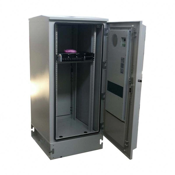
The main components of a splice box are the splice cassette that picks up the fibers and their reserves, and the front panel which contains different connectors for transmitting signals via copper or fiber optic cables. A splice box (also known as splice distributor) is a housing in which fiber optic cables begin or end. Fiber optics are fanned out in splice boxes that are situated at the end of fiber optic transmission paths. It typically consists of two parts: an outer housing and an internal structure. In this response, we will focus on the. The FSB series of indoor wall mount enclosures are designed for centralized splice-only applications. These boxes are well suited as optical cable splice collection points for DAS (Distributed Antenna Systems), MTU (Multi-Tenant Unit) commercial business applications, and MDU (Multi-Dwelling Unit). Fiber optic splice closures permanently connect two fiber optic cables together and have a splice that protects the components. The optical cable connection part, that is, the optical cable joint, is the part that protects the connection between two or more optical cables by the optical cable. Splicing refers to the permanent connection of two optical fibers to form a continuous optical connection.
[PDF]
Cambodia Fibre Optic Communication Networks Co., Ltd (CFOCN) has requested the Ministry of Public Works and Transport (MPWT) for approval to undertake a project involving the drilling and installation of new fibre optic cables across Cambodia's nine major provinces. This request was discussed during a meeting. Established since 2022, and obtained a license from Telecommunication Regulator of Cambodia (TRC) Who We Are? Established in 2022, and obtained a license from the Telecommunication Regulator of Cambodia (TRC). – Cambodia Licensed Provider for Operation and Provision of Telecommunications Cable. Telcotech is Cambodia's trusted choice of Telecommunication Infrastructure and Associated Services Provider. With a 30,000-kilometer-long. The project company comprises investment of two fiber optic telecommunication networks which are the undersea fiber optic cable Asia-Africa-Europe 1 (AAE-1) and the land cable network (the 'Project'), as detailed in the following report. The project will be developed by (Cambodia) Fiber Optic. Phnom Penh (FN), Aug. 14 – Telcotech is one of the market leaders for infrastructure in Cambodia, subsea cable and also connectivity in the region, announced the cooperation with Huawei building Cambodia's first nationwide next generation transport network. It is understood that the network will.
[PDF]

Explore 74 top manufacturers and suppliers of Optical Testing Instruments in our comprehensive photonics buyers' guide. An optical testing instrument is a device or system used to evaluate and measure the performance, quality, and characteristics of optical components. Source Photonics, founded in 1988 and based in Los Angeles, California, is a technology company that specializes in optical transceivers and data connectivity solutions. The company provides a wide range of products tailored for data centers, broadband, and optical transmission, serving. CACI designs and manufactures optical communications terminals for all of the major orbits in which our customer missions operate. These bespoke solutions are being manufactured in Orlando at CACI's space manufacturing and testing facility, which opened in June 2022. The facility is dedicated to. Manufacturer of standard and custom opticaltestequipment including microscopes, pocket comparators, disc gages, grids, scales, strips, slits, and micrometers. Suitable for optical, gaging, imaging, and calibration applications. Serves aviation industry. Lapmaster Wolters is estimated to have. Optical transceivers are devices that convert electrical signals into optical signals for transmission and reception. They are primarily used in communication systems that employ optical fiber cables, serving the purpose of signal conversion between the transmitting and receiving ends.
[PDF]

Optical Fiber Communication (OFC) revolutionizes modern telecommunications, enabling rapid data transfer across long distances with minimal signal loss. This comprehensive review explores OFC's historical evolution, core principles, components, and versatile applications. It traces OFC's. Additionally, optical fiber is lightweight and less susceptible to noise (no electromagnetic induction). Optical fiber consists of a cylindrical core that propagates light and a concentric cladding that surrounds it. The cladding's refractive index is slightly smaller than that of the core, which. Fibre optics and optical communications is the use of thin strands of glass for sending information encoded into light over long distances. Total internal reflection prevents light inserted into one end of the fibre from escaping through the sides. Keywords: Optical fibers, communication systems, data. Figure 1: Illustration of the inverse-square law of light intensity – the light's intensity diminishes with the square of the distance, which free-space optical signals must overcome (leading to very weak reception at long range) Figure 1 illustrates how light intensity decreases as distance.
[PDF]

Convenient Supply Solutions for Oscilloscope Probes Products for resellers and dealers based in Uzbekistan serving Tashkent, Namangan, Samarkand, Andijan, Bukhara, Nukus, Qarshi, Kokand, Chirchiq, Fergana and more. Lenses made from all optical glasses, including Si, CaF2, Ge, ZnSe, ZnS, quartz, and sapphire: Standard lenses in all common designs as well. Optical surface inspection detects minimal defects. This way, you produce your workpieces with consistently high quality. com is a proven supplier of Oscilloscope Probes products dealing major product. According to Volza's Optical,Instrument Import analytics, 698 verified Optical,Instrument buyers in Uzbekistan have imported Shipments from 661 global suppliers. OOO HILBRO accounted for 51% of Uzbekistan's total imports with (1,143 shipments). IP OOO. Compare products based on your own technical specification criteria. How does our search work? With MEET OPTICS search you get direct access to our database of thousands of optical components from providers worldwide. Prices and product specifications directly listed from optical component. Copyright © 2022 GOC-UZ. See our terms of use and privacy policy. Find and discover Optical Equipment buyers & importers for all products in Uzbekistan, featuring details on their shipment activities, trade volumes, trading partners, and more. Subscribe to global trade data intelligence to.
[PDF]

Wavelength measurement devices work on the principle of measuring the distance between two consecutive points of an electromagnetic wave in terms of wavelengths. This can be achieved through various methods, including spectrophotometry, interferometry, or the use of optical spectrum. These devices accurately determine the wavelength of light, providing crucial information for research, quality control, and diagnostics. Wavelength is a fundamental property of light and can significantly affect its interaction with matter. Precise wavelength measurement allows scientists to. Wavelength meters are interferometers used to measure wavelengths of laser beams. The devices are mounted on benches or desktops. They generate numerical values identifying pulsed and continuous wave lasers. They enable. This article provides a comprehensive explanation of the concept of wavelength in physics, particularly in optics and photonics. It defines wavelength as the spatial period of a wave, explaining its mathematical relationship to the wavenumber, optical frequency, and phase velocity. Accurate wavelength measurement is crucial in fields like physics, chemistry, astronomy, and engineering. Each method offers unique insights and varying degrees of precision.
[PDF]

Match trench method with the correct underground fiber structure (GYTS, GYTA53, GYTY53, micro-duct). Control pulling tension and bend radius – most damage happens during installation, not operation. Plan depth, backfill and warning markers early to reduce maintenance risk and. ion) and “ Installed” (after installation). The following formulas may be used to determine general guidelines for installing Corning Optical Communications fiber optic cable; however, refer to the cable specifi simply double the minimum working bend radius. Split cable guides and split 40-in. 1. 01 This best practices procedure provides general information for the installation of fiber optic cables in direct buried applications. The methods described are intended for guideline use only, as it is impossible to cover all the various conditions that may arise during an installation. Individual. Fiber optic cable transmits data as pulses of light through thin strands of glass, offering superior bandwidth and distance capabilities compared to traditional copper wiring. Direct burial is a common and highly effective method for external installations. ■ 1). Conventional trenching is suitable for open areas, while narrow trenching or horizontal directional drilling (HDD) is often preferred in urban or high-traffic environments to minimize disruption during underground fiber optic cable installation. Using Conduits to Protect Underground Fiber Cables In.
[PDF]

The Intellinet Network Solutions 10 Gigabit Fiber SFP+ Optical Transceiver Module (model 507479) is fully hot-pluggable, and that allows you to install the module without rebooting your network switch for uninterrupted network traffic. Intellinet Network Solutions 10GBase-LR Fiber SFP+ Optical Transceiver Module, model 507479, is the right choice when it comes to connecting two buildings at 10 GbE speeds with single mode fiber. That's a 10 Gbps connection up to a distance of 10 km (or 6.2 miles). The transceiver comes in a mini-GBIC form factor, making it ideal for environments that require many fiber connections by taking up less space in your cabinet and/or computer room. Compatibility in your network is everything, and the Intellinet Network Solutions SFP+ Transceiver Module (model 507479) delivers. Use it with any Intellinet Network Solutions SFP+ equipped network switch or any other MSA compliant SFP+ enabled switch. And since the Intellinet Network Solutions SFP+ transceiver module is set to broadcast the vendor. The Intellinet Network Solutions 10 Gigabit Fiber SFP+ Optical Transceiver Module (model 507479) supports standard digital diagnostics monitoring (DDM) functions, also known as digital optical monitoring (DOM). This gives the user the ability to monitor parameters of the SFP, such as optical output power, optical input power, temperature, laser bia.
[PDF]

To use a power meter for fiber optic testing, always clean connectors first with lint-free wipes or click-to-clean tools. Select the correct wavelength and set your reference. You measure optical power in dBm or insertion loss in dB. Consistent procedures ensure accuracy. Verify light travels from. The most basic fiber optic measurement is optical power from the end of a fiber. This measurement is the basis for loss measurements as well as the power from a source or presented at a receiver. Typically both transmitters and receivers have receptacles for fiber optic connectors, so measuring the. An optical power meter measures the strength of light traveling through a fiber optic cable, giving you a reading in dBm (decibels relative to one milliwatt). This article will guide you through the methods, instruments, and key considerations for measuring fiber. Fiber optic cabling is the high-performance core of today's datacom networks. As network speeds and bandwidth demands increase, fiber performance requirements have become more stringent. Fiber testing is more important than ever. An OPM uses a photodiode to generate an electrical current proportional to optical power.
[PDF]
In 1880, and his assistant created a very early precursor to fiber-optic communications, the, at Bell's newly established in. Bell considered it his most important invention. The device allowed for the of sound on a beam of light. On June 3, 1880, Bell conducted the world's first wireless transmission between two buildings, some 213 meters apart. Due to its use of an atmospher.
[PDF]

The BA-1 device produces step attenuation of a laser beam to a maximum of about 44 dB . With the preattenuator beam splitter, denoted by SI, this range can be extended as much as another 3 0 dB. The various low level beams generated by BA-1 can be used for detector respon-sivity and. Danielson, B. (1977), Measurement procedures for the optical beam splitter attenuation device BA-1:,, National Institute of Standards and Technology, Gaithersburg, MD, , https://doi. 77-858 (Accessed February 10, 2025) If you have any questions about this publication or. Beam splitters are optical devices that play a crucial role in various scientific and industrial applications. They are used to divide a beam of light into two or more separate beams. NBS interagency report is a publication of the U. The papers are in the public domain and are not subject to copyright in the United States. The BA-1 system is designed for use at. The attenuation ratios of these wavelengths are calculated values. An analysis of the estimated uncertainties is. SPLITTER ATTENUATION DEVICE BA-1 B. Danielson Measurer::ent procedures are described for the step attenuation of laser bearriS up to 44 dB using a specially constructed attenua- tor box (BA-1). a laser beam) into two (or sometimes more) beams, which may or may not have the same optical power (radiant flux).
[PDF]

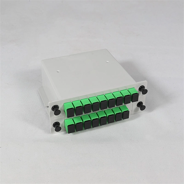
An Optical Splitter, also known as a beam splitter, is a passive optical device that divides a single input optical signal into two or more output signals. Conversely, it can also combine multiple signals into one. Knowing the difference between a splitter and an optical coupler helps you build better networks. You make your network work better when you pick the right device for each job. You can connect many users to one port with 1:n or 2:n splitters. By dividing a single optical signal from a central Optical Line Terminal (OLT) into multiple outputs for Optical Network Terminals (ONTs) at users' homes, splitters eliminate the need for dedicated fibers to each residence—slashing infrastructure costs while scaling network reach. This guide. In a Passive Optical Network (PON), a single optical fiber carries massive amounts of data using light. Signal Input: The fiber splitter receives the optical signal from the upstream network node and enters the splitter through the input fiber. Signal Distribution: Inside the splitter, according to the design structure and different. Splitters are passive optical devices that divide or combine optical signals, and they come in various types, including power splitters, uneven splitters, and wavelength-division multiplexing (WDM) splitters. Each type serves specific applications, enabling efficient use of optical infrastructure.
[PDF]
