HUAWEI WDM replacing the optical module video shows you how to replace an optical module. HUAWEI WDM Documentation:. Single-fiber bidirectional (BIDI) optical modules must be used in pairs. For example, SFP-10G-BXD1 must be used with SFP-10G-BXU1. If the SFP-10G-ER-1310 is connected. SFP Work on Cisco/Huawei/Arista/Juniper/MikroTik/Aruba/H3C/Fontinet/Ruijie etc Check my profile for tips. WhatsApp:86 13528869091 How to disassemble a 10G optical module? How to disassemble a 10G optical module?. Huawei's hn8145x6 idle fish costs more than 400 yuan, which is twice as expensive as the hs8145x6 and k662 previously disassembled. The reason for the price is that 10G Optical fiber module is more expensive, and the CPU is also different. Take down the machine and see what's going on. HUAWEI WDM Documentation:. The SFP (Small Form Factor Pluggable) or SFP+ transceiver is a critical component of fiber optic network cabling. It is used as a hot-swappable I/O device that plugs into a module slot for Gigabit transport. Failure to install an SFP or SFP+ transceiver can cause damage to the transceiver and the. This article will explore best practices for deploying 10G optical modules and offer tips for troubleshooting and maintaining their performance to maximize the longevity and efficiency of your network. Deploying a 10G transceiver requires meticulous planning and adherence to best practices to.
[PDF]

Run the following command to view detailed optical module information on the device interface: display transceiver interface <interface-type> <interface-number> verbose The command output is divided into two parts:. Run the following command to view detailed optical module information on the device interface: display transceiver interface <interface-type> <interface-number> verbose The command output is divided into two parts:. When the optical module on an interface is faulty, you can run the display commands to view information about the optical module. Related Information Video Identify a Huawei-Certified Optical Module Run the display transceiver [ interface interface-type interface-number | slot slot-id ] [ verbose ]. During use, reading optical module information helps understand its real-time operating status, enabling faster troubleshooting of link abnormalities. The following uses the Moduletek SFP-10G-LR module connected to a Huawei S6700 switch as an example to introduce how to read information of the. See the interface module via the optical display command information, including general information of the optical module, manufacturing information, and alarm information. If it is not a Huawei-certified optical module, replace it with a Huawei-certified optical module. If the optical module is installed on a GE port, run the display interfaceGigabitEthernet x/x/x command to view port information when the optical module.
[PDF]

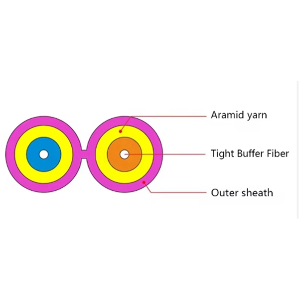
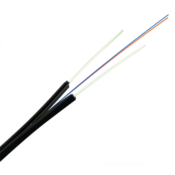
Its typical transmission distance is 20km or 40km. For instance, some ethernet switch manufacturers refer to the 1000BASE-LH SFP as the 1G 1310nm 40km SFP transceiver, which indicates the module's transmission distance and wavelength. The 10G SFP+ dual-fiber optical module is a small pluggable optical transceiver that adopts a dual-fiber bidirectional design. It completes signal transmission (Tx) and reception (Rx) through two independent optical fibers, ensuring the stability and reliability of signal transmission. An SFP (Small Form-factor Pluggable) module transmits data over fiber using specific wavelengths and power levels, which directly influence how far the signal can travel before degradation occurs. This is why two. If the optical module works at a wavelength near 850nm (880nm) or 910nm (940nm), then the module is a multi-mode fiber (MMF) optical transceiver, and if the working wavelength is 1310nm or 1550nm, it is a single-mode fiber (SMF)optical module. Generally, the maximum transmission distance(generally. The transmission distance of optical transceiver modules is divided into short distance, medium distance, and long distance. A 1-core module uses a single fiber core for data transmission, while a 2-core module uses two cores. o Think of a highway. Chromatic dispersion This is a key factor affecting single mode fiber distance.
[PDF]
A passive optical network (PON) is a point-to-multipoint fiber network architecture that uses optical splitters to deliver high-bandwidth services from a single fiber to multiple end users without requiring active electronics in the field. While there are many subtle differences, a clear distinction between active optical networking and PON topology is PON's use of a. A passive optical network (PON) is a fiber-optic telecommunications network that uses only unpowered devices to carry signals, as opposed to electronic equipment. In practice, PONs are typically used for the last mile between Internet service providers (ISP) and their customers. In this use, a PON. A passive optical network sends data as light through fiber cables. You get internet, TV, and phone services with fewer cables and no powered splitters between you and your provider. What equipment do you need for PON at home? You need an optical network unit (ONU) at your home. By eliminating powered components between the service. Technology drives the broader adoption of passive optical LAN (also known as a passive optical local area network) across various sectors. Not having a long history as a passive optical network (PON), it is a better replacement for copper-based LANs in local area networks. This article covers every.
[PDF]
If the optical module is faulty, replace it. If the fault is caused by incorrect configuration or networking environment, change the configuration or networking environment. If the fault persists, contact technical support personnel. Check whether the optical modules are. port is disconnected due to optical module faulty (0xF0060004) on port is disconnected. Config log : As the port is disconnected from the application server or other devices. If the optical module is not completely installed in position and the latch boss is not secured, the device cannot identify the optical module. Solution: To solve this problem, you can follow these steps: Check if the fiber and optical modules are compatible. Perform a. Optical modules are widely used in switches, network interface cards (NICs), routers, and other communication devices. During use, reading optical module information helps understand its real-time operating status, enabling faster troubleshooting of link abnormalities. Indicates the MIB object ID of the alarm. See the. If it is not a Huawei-certified optical module, replace it with a Huawei-certified optical module.
[PDF]
This article compares typical cost ranges across speeds and transceiver types, explains why prices vary, and gives practical guidance for choosing the right optics for a given budget and performance requirement. This article helps network architects and procurement teams run a practical cost analysis for implementing Open RAN using pluggable optical modules across fronthaul and midhaul. All price bands below are market-observed ranges (OEM-branded vs. As per our latest research, the 25G Fronthaul Optical Module market size reached USD 1. 42 billion globally in 2024, demonstrating robust growth driven by the accelerating deployment of 5G wireless networks and expanding data center infrastructure. The market is projected to grow at a CAGR of 18. 7% from 2025 to 2033, reaching a forecasted value of USD 4. 47. The 5G fronthaul optical transceiver modules market is experiencing rapid evolution driven by the global rollout of 5G networks. These modules form the backbone of high-capacity, low-latency communication infrastructure essential for 5G deployment.
[PDF]
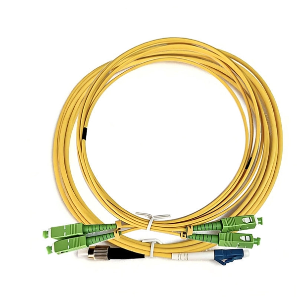
The SFP-10G-ER transceiver module is the proven, standards-based workhorse for extending 10 Gigabit Ethernet up to 40km over cost-effective single-mode fiber. This hot-pluggable SFP+ transceiver is engineered to transmit 10Gbps data streams over single-mode fiber (SMF) for link lengths up to 40 kilometers, making it indispensable for metro Ethernet, campus backbone networks, enterprise data center interconnects (DCIs), and telecom access networks. 10GBASE-LR SFP+ Module: 10Gb/s data rate, Single-Mode, duplex LC connector, 1310nm wavelength, the transmission distance up to 10km, working temperature: 0℃ ~ 70℃, Tx Power (dBm): -6. Equipped with an LC connector. Experience reliable high-speed networking with the VIVOTEK SFP-2000-SM13-10, a 10 Gigabit Mini GBIC designed for enhanced performance. Utilizing 10GBase-X technology, it delivers data transfer speeds up to 10 Gbps over compatible cables, ensuring efficient and scalable connectivity. This module. The 10 Gigabit Singlemode SFP+ Transceivers provide high-performance, reliable connectivity for modern 10 Gigabit Ethernet (10GbE) networks. These transceivers are designed for singlemode fiber, offering superior performance over long distances. Whether you're working on data centers, campus. These SFP transceiver modules come in a metal housing that reduces electromagnetic interference and increases their durability.
[PDF]

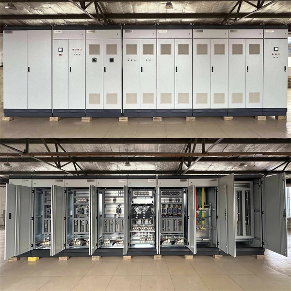
As a leading manufacturer and supplier of fiber optic components, we consistently provide high-quality fiber optic components, fiber optic active connectors, optical splitters, fiber optic adapters, fiber optic cables and other products. Huijue Group's energy storage solutions (30 kWh to 30 MWh) cover cost management, backup power, and microgrids. To cope with the problem of no or difficult grid access for base stations, and in line with the policy trend of energy saving and emission reduction, Huijue Group has launched an. Founded in 2002, Huijue Group is a high-tech service provider integrating intelligent energy storage equipment and computer intelligent network communication system integration and application. Huijue Network's products are exported to Europe, North America, Southeast Asia and other countries and. Shanghai Technology R&D Center was established, opening the mode of independent R&D and innovation Self-owned brand products enter the radio and television and operator markets Established more than 20 offices in China. The group owns 6 wholly-owned subsidiaries and 4 major production bases located in Shanghai, Yangzhou, Haian, and. Premier producer of solar energy storage solutions & Site-specific Products, excelling in quality & efficiency.
[PDF]

These general purpose fiber clamps provide easy means for incorporating glass or plastic optical fibers into optomechanical post assemblies or SM1-threaded components. The precision V-groove and rubber pad are designed to clamp onto the buffer of single mode or multimode fibers without damaging. Harwin supplies a range of surface-mount shield can clips to provide a straight-forward, easy-to-use board-level shielding solution. The combination of SMT clips with a shield can provides a simple and cost-effective method of shielding vulnerable or EMI-radiating board components. Harwin's shield. Check each product page for other buying options. 2-piece kit Fiber optical thermal stripper M8 & fiber optical cleaning clip compatible with bare fiber/bundle and ribbon fiber for 1-48 core dual heating mode and 8-level temperature regulation. Need help?. FPH Fiber Chucks and Holders are designed to terminate bare optical fibers and provide precise coupling and mounting within optical systems. Compatible strain relief boots and fiber clamps are also available. Clamps are larger than clips and designed to hold multiple cables and wires together. Blind plugs are used to close. 1-800-363-1992 Have any questions? Talk with us directly using LiveChat.
[PDF]

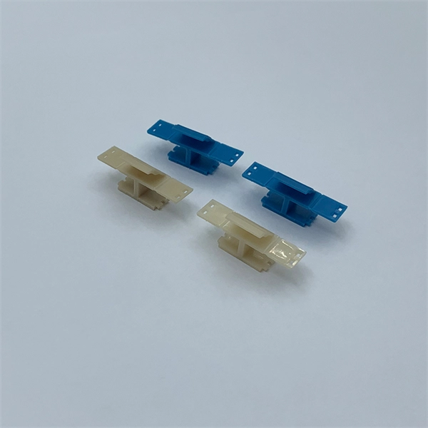
It involves encapsulating the optical chip in a metal box filled with inert gas (usually helium) to protect the optical elements from external environmental influences and enhance heat dissipation. COB, BOX, and TO-CAN packaging each offer unique advantages tailored to specific applications. COB packaging integrates components directly onto a PCB, enabling miniaturization and cost efficiency. BOX packaging seals optical chips in a metal enclosure with inert gas, ensuring long-term stability. The COB process refers to a technology that directly mounts bare chips onto a printed circuit board (PCB), connects them via gold wire bonding, and then encapsulates and protects the chips and wires using organic adhesive. Compared with conventional processes, the COB process offers high packaging. Box, COB, and TO can are currently the most prevalent packaging forms for optical components. Box packaging, also known as hermetic sealing, has a long history. Common optical device packaging methods include COB (chip-on-board packaging), BOX and coaxial packaging. What is COB technology? COB (Chip on board) is a form of packaging that directly bonds the. The invention provides an SFP28 SR optical module structure of a COB process, and belongs to the field of optical module structures. The micro-optical module comprises a shell, an unlocking mechanism, an EMI shielding structure, a circuit board, a micro-optical module arranged at one end of the.
[PDF]

BBU end can be connected to CWDM coarse wavelength division multiplexer through CWDM color optical module and OS2 single mode optical fiber patch cord, and then transmitted to CWDM coarse wavelength division multiplexer with one or two optical fibers. The operation of base stations requires a large number of optical modules for interconnection between devices, and we will talk about the application of optical modules in mobile communication base stations. Communication base station is composed of machine room, base station, antenna, feeder. The base station can be divided into two modules: the RRU for transmitting signals and the BBU for processing signals. The BBU is small and exquisite, with low power consumption, while the RRU is large and has high power consumption. In 4G networks, the optical modules used to connect BBU and RRU are mainly gigabit to 10Gbit optical modules. In modern server racks, the wrong optical choice can silently tax performance: queues grow, link training becomes flaky, and operators end up swapping modules mid-quarter. In 5G networks, CPRI is also upgraded to eCPRI. Currently, 5G of the bearer network mainly uses 25Gbps optical.
[PDF]

It emits a stable red light driven by a constant current source, which is coupled into the optical fiber through an interface to perform fiber fault detection functions. These include checking fiber connectivity and locating faults such as fiber breaks and bends. The B5 Rechargeable Red Light Pen is a professional 650nm visual fault locator designed for fiber optic network maintenance, installation, and troubleshooting. Its advanced rotary automatic lift laser head ensures smooth operation, while the integrated LED lighting improves visibility in low-light. Luxbond LBTEK Fiber Optic Red Light Pen (also known as a pen-style visual fault locator or fiber optic fault detector) uses a 650 nm semiconductor laser as the light source. Note: Meant for use with polished, terminated fiber cables. Always insert and remove the fiber connector without bending the connector to avoid breaking. The RPEN-210 is a necessity tool that should not be missing from any fiber plant manager or fiber optic installing technician. The Visual Fault Locator (VFL) Pen has a visible red light source centered on 650nm. Tool sends visible light over a fiber strand with a 10mW power, good enough to reach. ● Practical Design: Small size and lightweight, pen-type design with pouch make it portable. Design with a stainless steel head and aluminum body to prevent crash and dust, the case ground design prevents ESD damage efficiently Temp. Only registered users can write questions.
[PDF]
Instantly reprogram, test, and unlock universal compatibility for every optical module — with full diagnostics and OTA updates built in. It lets you check the health of any SFP or QSFP module and program them effortlessly in seconds. We're cutting prices across the entire Ubiquiti SFP lineup — up. SFPTotal devices are full-compatible with official software SFPTotal Wizard which provides a convenient interface that allows to read, decode, edit and write changes to the memory of optical transceivers GBIC, SFP, SFP+, SFP28, XFP, QSFP+, QSFP28 and QSFP-DD form factors. Copy or write optical module profiles instantly. MFT (Mellanox/NVIDIA Firmware Tools) is a set of firmware management utilities for querying firmware details, performing firmware upgrades, and other configuration tasks. It includes four main components: mst, mlxburn, flint, and Debug Utilities. For full specifications, refer to the official. Reprogram and Diagnose Optical Modules Instantly with SFP Wizard The Ubiquiti UACC-SFP-Wizard is a portable, all-in-one optical module programmer and diagnostic tool designed for IT.
[PDF]
When the optical switch module's switching interfaces are all busy or an optical signal needs signal regeneration through an OEO conversion process, the electronic module is used. In modern optical transport networks, optical cross‑connect (OXC) devices are essential for high-speed, flexible signal routing. An OXC switches optical signals between fiber inputs and outputs without converting them to electrical signals, enabling true all-optical routing. In the 1980s, when transmission speeds supported by optical fibers increased from 45 Mbit/s to 2. In essence, an OXC uses photonic switching fabric to route wavelength channels from any incoming fiber to any outgoing fiber. OXC (optical cross-connect) is an evolved version of ROADM (Reconfigurable Optical Add-Drop Multiplexer). As the core switching unit of the optical network, the scalability and economic efficiency of the optical cross-connect (OXC) not only determine the flexibility of the network topology, but. Vendors such as LINK-PP provide comprehensive transceiver and interconnect solutions that ensure OCS architectures perform at their highest potential. This article explores OCS fundamentals, its benefits, use cases, and how LINK-PP optical module solutions complement these networks. Compared with traditional ROADM based on separate boards and inter-board fiber patch cords, OXC uses integrated interconnections to build an all-optical switching resource pool, achieving highly integrated, fiber.
[PDF]

First, inspect the optical module appearance for physical damage, cracks, missing components, poor solder joints, or burn marks. Next, compare voltage, resistance, and waveform parameters between a normal it and the suspected faulty one, both in powered and unpowered states. As core components of optical communication systems, the proper installation and use of optical modules directly impacts network stability. This article systematically identifies common anomalies during optical module installation. However, during installation and daily operation, various issues may arise. The following will introduce the causes of various problems and how to deal with them. Optical module method/step 1. During the test, the value of the module I BiasADC is 0, and the TXLOP-ADC and. These compact devices convert electrical signals to optical signals and vice versa, enabling data transmission over fiber optic cables. While generally reliable, failures do occur, leading to frustrating downtime, performance degradation, and costly troubleshooting. This comprehensive guide details. Have you ever dealt with sudden network drops from faulty optical modules? Issues like this cannot only break communications, but they can really jeopardize business continuity.
[PDF]