This guide provides instruction on how to install and configure your MS130R series switch. For more switch installation guides, refer to the switch installation guides section on. This guide provides step-by-step instructions for installing two common types of industrial switches: rack-mount, and DIN-rail switches. Choose the Installation Location: Select an appropriate spot on the DIN rail for mounting. This chapter describes how to start your switch and how to interpret the power-on self-test (POST) that ensures proper operation. No prior experience needed—just follow along and you'll have your switch installed and running in minutes. more In this video you'll see a complete, step-by-step guide to mounting. This typeface indicates command syntax, or represents information as it is displayed on the screen. When you see the word enter in this guide, you must type something, and then press the Return or Enter key. Do not press the Return or Enter key when an instruction simply says type. Here, we explore the four most common installation methods for industrial switches: Desktop installation is the most straightforward approach— placing the switch like a small box directly on a table, control panel surface, or equipment rack without extra fixtures. Simple setup: No tools required.
[PDF]

There are 48 bicolor LEDs (green/amber) for the first 48 SFP+ ports and 16 tricolor LEDs (green/amber/white) for the SFP-DD ports. The last set of LEDs pulse once in white before indicating the FC port status in green or amber. When it blinks white twice, it shows the status of the second port of the SFP-DD. The port status LEDs for the FC ports are arranged left and right to correspond to the upper and lower ports respectively in each pair. LEDs on the port side of the switch Table 1. LEDs on Cisco Catalyst 9500 Series Switches 1 Available only on switches with 10G ports. System LED Indicator System is not operational. System is operating normally. As a group or individually, the LEDs show information about the switch and about the ports Preventing Overload - Each port that provides PoE has a maximum power it can deliver. Three LEDs are used on each port. Ports on the Cisco Catalyst switch do not have LEDs. Not the question you're searching for? Each. Number of LEDs per port - Ports that cannot be split; for example, 1G ports must have 1 LED per port. Location - A port LED should be placed right above the.
[PDF]
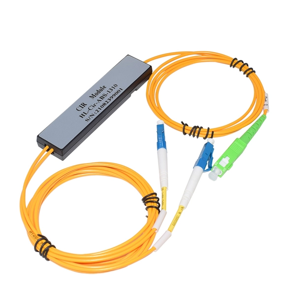
This guide demystifies fiber optic splitters, explaining their design, operating principles, types, key specifications, and real-world applications. Whether you're a network engineer designing a PON (Passive Optical Network) or a homeowner curious about how your fiber connection works. I'm planning to use a TP-Link MC220L transceiver to convert the optical signal to ethernet. This ethernet will then go through a 1 Gbit/s switch, and rout two ethernet cables to each floor. On each floor each ethernet cable will be connected to a router, which will then distribute the internet. DWDM/CWDM is like a two-edged sword. For a small fee (the procurement of the modules and the circulator) you can split/splice one physical fibre optic cable into multiple pairs. The downside is that once you loose your one-and-only fibre link (to a cable-hunting-buck-hoe) then you're in trouble. Fiber optic splitters enable the division of optical signals into multiple paths, allowing information to be distributed to multiple subscribers or devices simultaneously. Understanding the inner workings of fiber optic splitters is crucial for network administrators, technicians, and anyone. The answer is yes, and it's a practice widely used in the industry to distribute signals to multiple destinations without degrading the signal quality significantly. What is Fiber Line.
[PDF]

Learn how to safely wire a single-pole (one way) light switch in this beginner-friendly tutorial. Whether you're replacing an old switch or doing your first DIY electrical project, this guide will walk you through every step — no experience needed!. more. This page contains wiring diagrams for household light switches and includes: a switch loop, single-pole switches, light dimmer, and a few choices for wiring an outlet/switch combo device. That's because virtually all light switches that control 120-volt fixtures are single-pole switches. Most light switches are also single-throw, which. Summary: Fully explained wiring diagrams and photos show how to wire switches including: single switches, 3-way switches, 4-way switches, and dimmer switches. and Be Sure to Subscribe! Make sure the circuit power has been turned off, and mark the circuit breaker or fuse to indicate that work is. A distribution board or distribution box is where the main power supply is distributed to multiple loads. And all the switching and protective devices are installed in the distribution box. Single Phase Distribution Box generally consists of Double Pole MCBs, Single Pole MCBs, and RCCBs. Wiring a single light switch may seem like a daunting task, but with the right tools, a bit of patience, and this comprehensive guide, you'll be able to tackle this DIY project with confidence. Remember, while this guide provides detailed instructions, always prioritize safety and consult a.
[PDF]
In part two of the 7-part series on how to wire a switch, I explain and demonstrate how to install the cables into a multi-gang box. The video focuses on steps that will both save time and simplify the process. In this video, we'll walk you through the process of wiring a home distribution box with a detailed connection diagram. Whether you're an electrician or a DIY enthusiast, this guide will help you understand the basics of home electrical distribution. Part of my job as a professional electrician is keeping my work neat and organized. A tidy work box makes it easier to install lights, switches, and outlets, and it helps future electricians to see what's going on inside the. Learn how to install a distribution box safely and correctly. Covers wiring, placement, standards, and expert tips for a compliant setup. A distribution box is the heart of any electrical system. It takes the incoming power and safely distributes it to different circuits throughout your building. If you're looking to install a switch box in your home or office, it's important to understand the process involved and the key steps to follow. And all the switching and protective devices are installed in the. According to NEC (National Electric Code: Article 1 00-Definitions), a Main Panel (also known as Panelboard, load center, breaker box and distribution board etc. ) is a cabinet or cutout box which contains on controlling and protective devices (such as circuit breakers, fuses, switches etc.
[PDF]

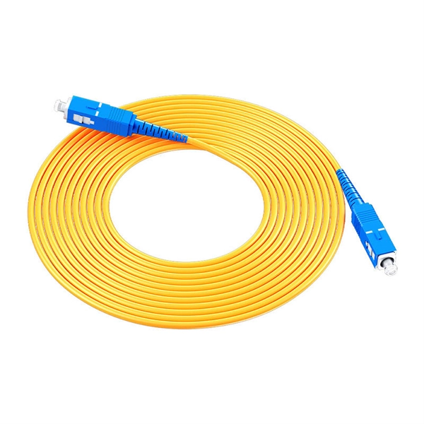
Connect the fiber optic cable: Attach the fiber optic cable's connector to the transceiver module on the switch. Make sure the connector type (e., SC, LC) matches the transceiver module. In addition, fiber cables can transmit data over several kilometers without signal degradation, making them ideal for connecting switches in large campus networks and between different buildings. As they do not emit electromagnetic signals, they're difficult to tap and secure against eavesdropping. Fiber optic cabling is increasingly used to connect network switches and other datacom equipment, especially in long-distance and mission-critical applications. Fiber provides: Increased internet signal bandwidth. Most modern fiber-enabled network switches require an SFP transceiver module. As we speak I just have optic fibre (Community Fibre) connected to my Huawei modem / Linksys Velop which will be connected to a new POE switch (need to identify the best model to be compatible with my optic fibre extension project). The objective is to run 1 or 2 additional optic fibre from the. Choose an SFP module based on the fiber optic cabling that will be connected to the network switches. SFP transceiver modules almost always require two fiber optic cable strands. Even the most advanced optical transceivers can only perform at their peak when paired with properly installed, clean, and precisely managed fiber.
[PDF]
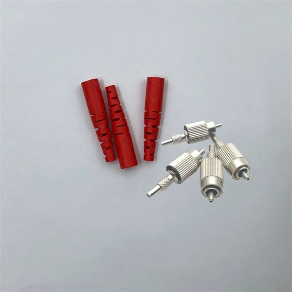
The SFP port is commonly found on Gigabit Ethernet switches and is primarily used for fiber optic device connections or for uplinking 1G switches to aggregation/core layer devices, providing higher-bandwidth links. You can add a compatible SFP transceiver module to the SFP port of. SFP ports enable Gigabit switches to connect to a variety of fiber and Ethernet cables and extend switching functionality throughout the network. Small form-factor pluggable is a hot-swappable interface used to connect network and storage switches and transfer data. Switches with SFP ports can. Choose an SFP module based on the fiber optic cabling that will be connected to the network switches. SFP transceiver modules almost always require two fiber optic cable strands. In this guide, we'll cover the following: What is an SFP port? Why is the SFP port important? SFP vs. QSFP28. Enterprise LANs use the RJ45 port on 100/1000BASE switches. It connects access layer devices and uplinks from desktop switches or directly to end devices. RJ45 ports remain essential for. An SFP switch uses Small Form-Factor Pluggable (SFP) modules to form a network switch for high-speed connectivity between devices. These interchangeable modules support various media types, including copper or fiber-optic cables, providing flexible networking options based on specific requirements.
[PDF]
MDC virtualizes one S7500X switch into multiple logical switches, enabling multiple services to share one core switch. The 1:N virtualization maximizes switch utilization, reduces network TCO, and ens.
[PDF]

The WannaCry ransomware attack was a worldwide cyberattack in May 2017 by the WannaCry ransomware cryptoworm, which targeted computers running the Microsoft Windows operating system by encrypting data and demanding ransom payments in the form of bitcoin cryptocurrency. It was propagated using EternalBlue, an exploit developed by the United States National Security Agen. DescriptionWannaCry is a , which targets computers running the by encrypting (locking) data and demanding ransom payments in the. The attack began on Friday, 12 May 2017, with evidence pointing to an initial infection in Asia at 07:44 UTC. The initial infection was likely through an exposed SMB port, rather than as initially ass. Linguistic analysis of the ransom notes suggested the authors were likely fluent in Chinese and proficient in English, as the versions of the notes in those languages appeared to be human-written while the rest seeme. The ransomware campaign was unprecedented in scale according to, which estimates that around 200,000 computers were infected across 150 countries. According to, the four mo.
[PDF]

How to Enable Trunking on Cisco Switch A trunk port carries many VLANs over one link between switches using 802. You turn it on with "switchport mode trunk" on the connecting interfaces at both ends. The port then adds a small VLAN ID to each frame and keeps traffic separate. A trunk is a point-to-point link between one or more Ethernet switch interfaces and another networking device such as a router or a switch. Ethernet trunks carry the traffic of multiple VLANs over a single link, and you can extend the VLANs across an entire network. You can configure a trunk on a. Understanding how to configure, verify, and troubleshoot 802. 1Q trunks is essential for building scalable switched networks. No intervening, non-trunking devices are allowed. It is important to note that ports on both ends of a port trunk group must have the same mode. Configuring a trunk port on a Cisco switch is essential for enabling the transmission of multiple VLANs across a single physical link. It is an important skill in Cisco's IT infrastructure training. Trunk ports allow switches to communicate with each other by carrying traffic for multiple VLANs. On Cisco switches, configuring trunk ports involves a precise understanding of protocols, commands, and best practices. This article provides a comprehensive guide to configuring and verifying trunk ports on Cisco switches, designed for network engineers, developers, and technology enthusiasts.
[PDF]

In this article, I'm going to describe how to set up Link Aggregation between two managed switches to provide connectivity, redundancy, and expanded bandwidth. Managed switches provide many advantages for a growing network, including support for VLANs, QoS, and Trunking. I touched on simple VLAN configuration a while back. in the United States and in other countries. App Store and the Apple logo are trademarks of Apple Inc., registered in the U. Google Play and the Google Play. Link Aggregation in UniFi allows you to combine two or more ethernet ports into one. The NVR is connect via Fibre to the USW as well. So. ? Any hints welcome! Archived post. New comments cannot be posted and votes cannot be cast. Imagine transforming multiple network cables into one giant, super-speed "data highway. " That's exactly what link aggregation does. It combines multiple Ethernet connections into a single logical connection, boosting speed, enhancing. Thank you for purchasing the Ubiquiti Networks® EdgeSwitch® XG. This Quick Start Guide is designed to guide you through installation and also includes warranty terms. TERMS OF USE: All Ethernet cabling runs must use CAT6A (or above). It is the professional installer's responsibility to follow local.
[PDF]
Switch Control is an accessibility feature in macOS designed to help users with mobility impairments interact with their computers using switches or adaptive devices. This article describes access control in Windows, which is the process of authorizing users, groups, and computers to access objects on the network or computer. Key concepts that make up access control are: Computers that are running a supported version of Windows can control the use of system and. Access Control is the process of restricting access to systems, networks, or resources based on predefined security policies. It determines who can access specific resources and what actions they can perform. Access control systems verify user identity using credentials such as passwords, PINs. With Use Other Devices for Switch Control, you can control your other Apple devices remotely on the same Wi-Fi network without adjusting any switch connections. This enables you to navigate your Mac or Apple TV with the same switch setup that you use to control your iPhone. Connect your devices to. The easy way to remotely connect with your home or work computer, or share your screen with others. Securely access your computer whenever you're away, using your phone, tablet, or another computer. This powerful tool can transform the way users navigate their macOS environment, allowing them to control the computer through.
[PDF]
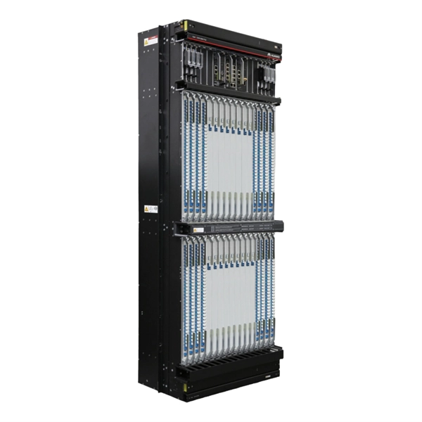
While both core and normal switches play crucial roles in maintaining efficient data flow, their functionality and applications vary significantly. This guide unpacks the core differences, helping you understand which type suits your networking needs. What Are Core and Normal. Core Layer: The core layer is the backbone of the hierarchy network. The primary transmission and routing of data signals take place at the core layer only. It consists of network switches that perform routing and switching of the data. The devices like high-capacity transmitters are placed in this. What are the Differences Between the Core Switch and Normal Switch? A core switch is not a type of switch, but a switch placed at the core layer (the backbone of the network). It provides a high-speed connection between different distribution layer devices. Edge = connects the internal network to the external WAN/Internet. Access vs Distribution: Access = user/device connectivity. Distribution = aggregates access, applies policies, routes traffic. Distribution vs Core: Distribution = policy. Data center-grade switches are characterized by high-quality business assurance and control recognition capabilities. They feature end-to-end flow control and backpressure mechanisms, ensuring stable and reliable data transmission, and smoothing out network surges. They offer higher reliability and.
[PDF]

The SX-153 is a next-generation, high-speed Ethernet switch designed for mission-critical Cyber, EW, SIGINT, and Comms applications across air, land, and sea platforms. The VX3940 is a 3U VPX Fully Managed L2/L3, 1/10/40/50 Gigabit Ethernet Switch. It is designed in alignment with the SOSA™ Technical Standard, as well as being compatible to a wide range of OpenVPX profiles and includes up to 32x 10GigE or 8x 40GigE ports (or combination of the two). Furthermore. All models of the 7050X3 Series offer flexible forwarding tables with a Unified Forwarding Table, latency from as low as 800 ns and a fully shared packet buffer of up to 32MB for superior burst absorption. Comprehensive support for a wide range of interface speeds including 10G, 25G, 40G, 50G and. In addition, the Cisco Nexus 5600 platform offers integrated line-rate Layer 2 and 3 capabilities with true 40 Gigabit Ethernet support, Cisco's programmable fabric innovation, Network Virtualization Using Generic Routing Encapsulation (NVGRE), Virtual Extensible LAN (VXLAN) bridging and routing. QFX5100 top-of-rack 10GbE/40GbE switches for the data center offer low latency, deployment versatility, and rich automation features. These switches provide universal building blocks for industry-standard architectures such as spine-and-leaf IP and EVPN fabrics.
[PDF]

Materials $450, labor $900, permits $0–$200, total $1,350–$1,550, per-breaker costs vary, overall project time 4–6 hours. Span reflects standard new breakers and enclosure. Mid-Range: 150–200A upgrade, some rerouting, outdoor panel, weatherproof box. Buyers typically pay a broad range for replacing a distribution box, driven by box size, amperage, wiring runs, and local labor rates. This article outlines the cost factors, price ranges, and practical budgeting advice for a U. Key cost drivers include panel amperage, indoor vs outdoor location, wiring length, and whether a full panel upgrade or rerouting is needed. The article outlines cost ranges, per-unit pricing, and practical. If you're planning a new commercial building or upgrading an existing space, our commercial electrical installation calculator can help you estimate what your project might cost. The average cost to hire an electrician to install or repair light fixtures, outlets, switches, or fans ranges from $141 to $419 with homeowners spending $280 on average. For larger electrical jobs like installing wiring or replacing an electrical panel, expect to pay $2,000 to $6,000.
[PDF]