The timeframe for splicing a fiber optic cable can vary depending on the type of splice, the equipment used, and the level of expertise of the technician. In this article, we will delve into the details of the splicing process and explore the. Fiber splicing involves several steps, each requiring attention to detail and precision: The first step is to prepare the fibers for splicing. This involves: The fiber splicing process itself involves: Once the splice is complete, the technician must test the connection to ensure it meets the. Mechanical splices are faster for emergency restoration but have higher typical loss (0. 1dB for fusion) and degrade over time in outdoor environments. A professional splice kit includes: Every splice starts with proper preparation: clean the work area, protect against wind, and. Downloadable one-page analysis available from The Fiber Optic Association also offers cleaving and splicing tips. A chart developed by Fiber Optic Association master instructor Joe Botha helps technicians calculate the amount of time it will take to conduct a fusion-splcing project. The FOA. So in essence, fiber optic splicing is a process used to join two separate fiber optic cables together. There are numerous use cases for fiber optic splicing. Another method of connecting optical fibers is termination or connectorization, which consists of processing the end of a fiber optic bundle so that it can be connected to other fibers or devices through fiber optic.
[PDF]

Learn how to splice fiber optic cable using fusion splicing with this complete step-by-step guide. Includes tools, best practices, loss standards (ITU-T G. 652), cost analysis, and FAQs for network engineers and installers. 5,398 fiber splicing stock photos, vectors, and illustrations are available royalty-free for download. Template technician Fiberoptic Fusion Splicing. Worker connecting for Cable Internet signal and Wire connection with Fiber Optic Fusion Splicing machine,fiber optic cable splice machine in work. Splicing fiber optic cable is an extremely important phase for making dependable, high-speed communication infrastructures. Regardless of the type of fiber network you're deploying, be it for telecom, enterprise data centers, or smart city infrastructure, fusion splicing provides the benefits of. In this guide, we cover the basics of fiber optic splicing, how to perform splicing using two different methods, and finally some best practices to perform good fiber splicing. Ensure Your Splicing Tools are Clean – #2. For network managers and technicians, a poor splice can lead to significant signal degradation, network downtime, and costly troubleshooting. At Turn-Key. 🔧 Watch a real-time fiber optic splicing demo in action! In this step-by-step tutorial, learn how to splice fiber optic cables like a pro — perfect for telecom technicians, network engineers, and field techs.
[PDF]
Distributed fibre optic sensing, including DTS and DTSS technologies, has a wide range of applications across various industries. Here are some key areas where these innovative technologies are making.
[PDF]
TeleGeography's comprehensive and regularly updated interactive map of the world's major submarine cable systems and landing stations. SIGET, El Salvador's telecom regulator, has chosen Liberty Networks as the provider to design, construct, deploy, and operate the country's first submarine cable. New 1,800 km cable will connect El Salvador to major international hubs, boosting high-speed internet capacity and resiliency. MIAMI. Liberty Networks is to deploy a new subsea cable linking El Salvador to Panama. MIAMI. The Submarine Cable Map is a free and regularly updated resource from TeleGeography. Its network has more than 150,000 km of fiber optics and connects 1,000+ nodes, 87,200+ on-net buildings, 100,000+ near-net buildings, 5,800+ on-net.
[PDF]

While optical power meters are the primary power measurement instrument, optical loss test sets (OLTSs) and optical time domain reflectometers (OTDRs) also measure power in testing loss. TIA standard test FOTP-95 covers the measurement of optical power. This measurement is the basis for loss measurements as well as the power from a source or presented at a receiver. Typically both transmitters and receivers have receptacles for fiber optic connectors, so measuring the. You need a power meter to measure power in a fiber optic system; most power meters come with a screw-on-adapter that matches the connector being tested and a little aid from the network electronics to turn on the transmitter. During the measurement of power, the meter must be set to the proper. Fluke Networks sets the standard in network testing with its advanced range of fiber optic power meters and fault locators, designed to ensure the highest precision in fiber optic meter readings and power evaluations. This is measured in decibels (dB). Splitters, fusion splices, connectors and. To use a power meter for fiber optic testing, always clean connectors first with lint-free wipes or click-to-clean tools. Select the correct wavelength and set your reference. Consistent procedures ensure accuracy.
[PDF]
Unlike DSL or cable, which use copper wires, fiber optic Internet service relies on optical fiber to transmit data. These fiber optic cables, made of glass or plastic, use light pulses instead of electrical signals, enabling high-speed Internet with low latency and reliable. Fiber optic internet is generally installed in the following 5 steps, which we'll dive deeper into throughout the article: A technician checks your area and prepares the connection from the neighborhood fiber network. A fiber cable (drop) is run from a nearby terminal that could be either a pole or. But how does fiber internet installation actually bring connectivity from a national backbone into your home? The process involves a combination of national infrastructure, local engineering, and property-level setup. In this guide, we'll break down the fiber installation process from start to. Fiber internet uses fiber optic cables instead of coaxial cables or metal wires to transmit data. If you've had the same internet plan for a few years or recently moved to a new area, you might find that fiber is now available near you. These cables employ light pulses to transmit information as opposed to the electrical impulses used by other cables. This enables fiber internet to achieve speeds that are.
[PDF]

Connect the fiber optic cable: Attach the fiber optic cable's connector to the transceiver module on the switch. Make sure the connector type (e., SC, LC) matches the transceiver module. In addition, fiber cables can transmit data over several kilometers without signal degradation, making them ideal for connecting switches in large campus networks and between different buildings. As they do not emit electromagnetic signals, they're difficult to tap and secure against eavesdropping. Fiber optic cabling is increasingly used to connect network switches and other datacom equipment, especially in long-distance and mission-critical applications. Fiber provides: Increased internet signal bandwidth. Most modern fiber-enabled network switches require an SFP transceiver module. As we speak I just have optic fibre (Community Fibre) connected to my Huawei modem / Linksys Velop which will be connected to a new POE switch (need to identify the best model to be compatible with my optic fibre extension project). The objective is to run 1 or 2 additional optic fibre from the. Choose an SFP module based on the fiber optic cabling that will be connected to the network switches. SFP transceiver modules almost always require two fiber optic cable strands. Even the most advanced optical transceivers can only perform at their peak when paired with properly installed, clean, and precisely managed fiber.
[PDF]

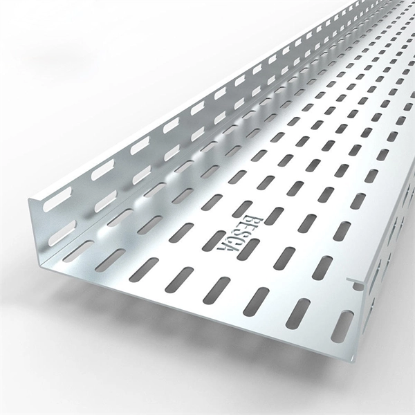
The NEC explicitly states that conductive optical fiber cables are not allowed to occupy the same cable tray or raceway as the aforementioned electrical conductors. The key difference here is safety. Nonconductive Optical Fiber Cables: These are typically indoor/outdoor rated fiber cables. This includes conductors for electric light, power, Class 1, non-power-limited. Maintaining proper separation between power, data, and limited energy cabling is foundational to system performance, safety, and code compliance. Separation isn't just an EMI precaution — it protects signaling, reduces rework, and ensures pathways meet inspection expectations across risers. Informational Note: 1 method of defining a cable that is low-smoke producing cable and fire-resistant cable is that the cable exhibits a maximum peak optical density of 0. 50 or less, an average optical density of 0. 52 m) or less when tested. Optical fiber cables shall be permitted to be installed in metal or listed nonmetallic cable tray systems. The previous requirements of 770. Most fiber cables are non-conductive so they can be placed alongside high voltage cables without any special insulation. cable installation must meet the NEC and local building code. Properly fiber rated fiber cables can use the same cable.
[PDF]
The PL-1000D simultaneously monitors up to 16 fiber strands, eight on the OTDR and eight on the OSA, and operates standalone over dark fiber, lighted fiber, or a third party network without impacting network traffic. The device monitors the entire D. The PL-1000D simultaneously monitors up to 16 fiber strands, eight on the OTDR and eight on the OSA, and operates standalone over dark fiber, lighted fiber, or a third party network without impacting network traffic. The device monitors the entire DWDM C-band spectrum and provides the optical spectrum, OSNR, and OTDR measurements of the fiber. The OTDR locates fiber cut by sending high powered optical pulses into the fiber and creating Rayleigh back-reflections. The returning signals are measured and calculated, indicating the accurate location and intensity of the fault. The OTDR supports GIS (Geographic Information System) using Rest API, enabling precise geographic location of disrupt. The OSA enables the user to monitor the OSNR and optical spectrum of each fiber and shows a full, accurate and detailed picture of the wavelengths used in the fiber. OSADiagram Graphical Display of the OSA, from PacketLight's LightWatch NMS Please contact usfor a quote or further assistance.
[PDF]

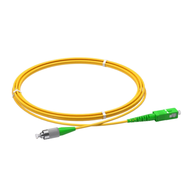
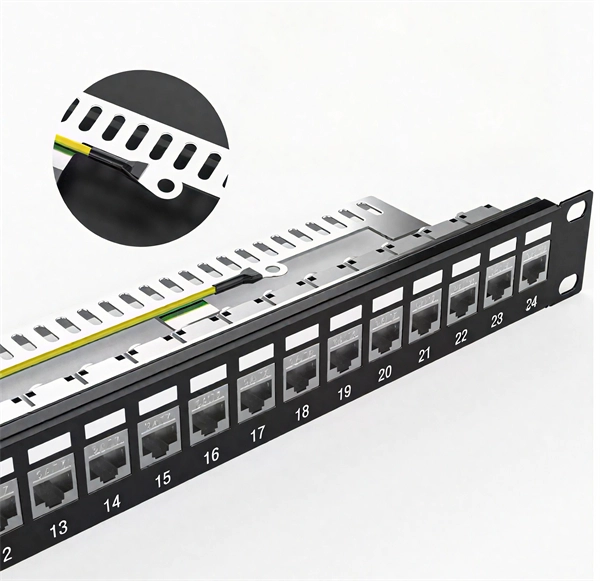
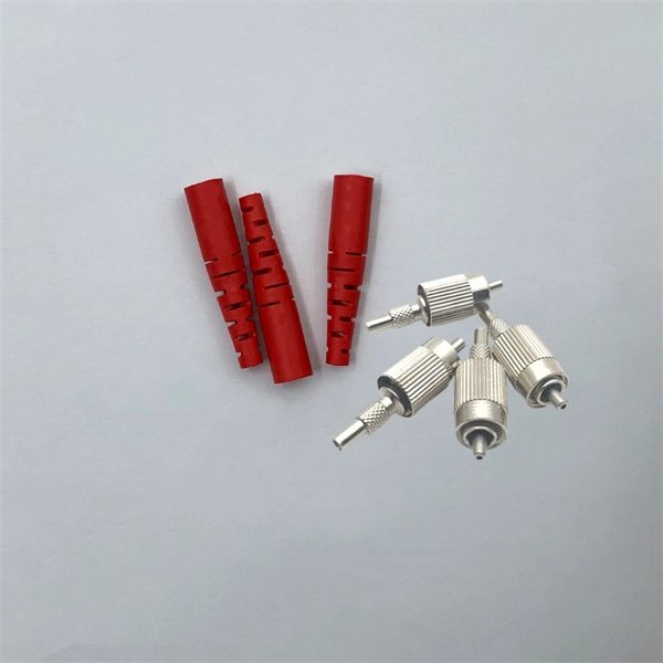
Fiber Optic Bundle Pigtails comprises a set of 12 optical pigtails. For ease of identification, these pigtails will come in 12 different colours and are used to be optically spliced with the optical fibers from the optical cable to enable network connection. Fiber optic pigtails are available in various types: Grouped by pigtail connector type, there are LC fiber optic pigtails, SC fiber pigtails and ST fiber pigtails, etc. And by fiber count, 6 fibers, 12. Fiber Optic Pigtails, also known as pigtailed fibers, consist of an optical fiber connector and a section of optical cable. Characterized by having an optical fiber connector on one end and a bare fiber end on the other, they are primarily used to connect optical transceivers or other optical. They are the bridge between fiber optic cables in the field and the equipment or patch panels that manage them. By combining factory-installed connectors with spliced bare fiber, pigtails ensure that network installers can create fast, reliable, and cost-effective terminations. Without pigtails. Executive Summary: A fiber optic pigtail is one of the most commonly specified yet least understood components in structured cabling. Fiber Optic Bundle Pigtails are. Traditional Fusion Splice-On Connectors with pigtails provide factory-polished performance with field-termination convenience within harsh environments. Mass fusion splicing can fuse up to all 12 fibers in one ribbon at once.
[PDF]
This report presents a comprehensive overview of the Serbian optical fiber cables market, the effect of recent high-impact world events on it, and a forecast for the market development in the medium term. The report provides a strategic analysis of the optical fiber cables market in Serbia and. The Serbian optical fiber cables market was finally on the rise to reach $X in 2025, after two years of decline. In general, consumption posted temperate growth. Conexio backbone network in Serbia was built in 2011-12. The entire network is running along the Highway (JP Putevi Srbije) which provides. The Skyline Belgrade Project has been carried out by renowned Israeli investor and developer AFI Europe, the creator of Airport City Belgrade, the first and only business park in the city, and Central Garden, the first apartment complex in Belgrad's center. AFI Europe, present on the Serbian market.
[PDF]
Glass fiber and plastic fiber is fragile. When individual fibers break, light transmission and uniformity are reduced. After the first few fibers break at a stress point, a chain reaction occurs, hastening t.
[PDF]

Libya's state-owned telecommunications company says the outage began when fiber-optic cables in eastern Libya were severed Tuesday. Internet and phone service were knocked out, with residents and journalists unable to reach those inside the city of Derna. CAIRO (AP) — A day-long communication outage in a flood-stricken city in eastern Libya further complicated the work of teams searching for bodies under the rubble and at sea Wednesday. The country's chief prosecutor, meanwhile, vowed to take "serious measures" to deliver justice for the victims of. On Tuesday, the Libyan Post Telecommunications and Information Technology Company (LPTIC) announced the disruption of Internet traffic in the country. LPTIC said in a statement that the disruption was “caused by a problem with the feeding equipment of the international submarine cable at the. Communications were severed Tuesday to the flood-hit Libyan city of Derna and journalists were asked to leave, a day after hundreds protested against authorities they blamed for the thousands of deaths. The company said in a statement, that the impact on Internet services on the submarine cable is due to an. In the aftermath of the devastating floods in Libya, Access Now urgently calls on the Libyan authorities to guarantee unrestricted and full access to the internet, as well as safeguard the fundamental rights and freedoms of the people, both in Derna and across the country. After Libya's devastating.
[PDF]
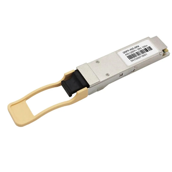
The SFP port is commonly found on Gigabit Ethernet switches and is primarily used for fiber optic device connections or for uplinking 1G switches to aggregation/core layer devices, providing higher-bandwidth links. You can add a compatible SFP transceiver module to the SFP port of. SFP ports enable Gigabit switches to connect to a variety of fiber and Ethernet cables and extend switching functionality throughout the network. Small form-factor pluggable is a hot-swappable interface used to connect network and storage switches and transfer data. Switches with SFP ports can. Choose an SFP module based on the fiber optic cabling that will be connected to the network switches. SFP transceiver modules almost always require two fiber optic cable strands. In this guide, we'll cover the following: What is an SFP port? Why is the SFP port important? SFP vs. QSFP28. Enterprise LANs use the RJ45 port on 100/1000BASE switches. It connects access layer devices and uplinks from desktop switches or directly to end devices. RJ45 ports remain essential for. An SFP switch uses Small Form-Factor Pluggable (SFP) modules to form a network switch for high-speed connectivity between devices. These interchangeable modules support various media types, including copper or fiber-optic cables, providing flexible networking options based on specific requirements.
[PDF]
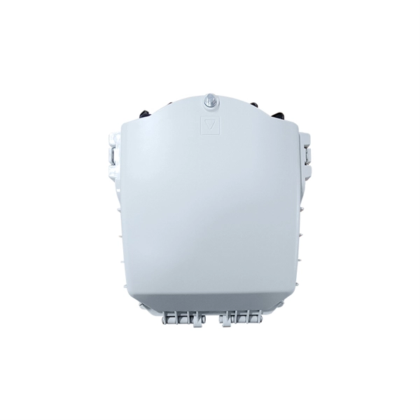
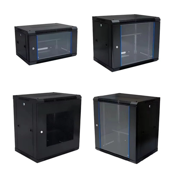
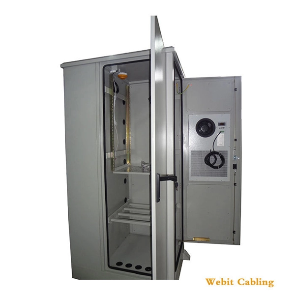
In short, the terminal box is the last structured node of the Fiber Optic System before service touches the subscriber. A typical PON topology (GPON, XGS-PON, or 25G PON) flows OLT → fiber distribution hub → passive splitters → distribution/drop fibers → premises. The terminal box sits at the. In broadband optical fiber access network, we often see the all kinds of fiber box such as fiber cabinet, fiber optic distribution box, fiber optic terminal box, multimedia box, and customer box. What is the difference between these fiber boxes. Let's look at the position of various fiber box in. A fiber cable (drop) is run from a nearby terminal that could be either a pole or an underground box) to your home. A small box on the outside of your home called a NID is installed and the fiber is coiled in there and connected to a fiber that runs into the home. The fiber is connected to an. Fiber Distribution Boxes (FDBs) are critical components in modern telecommunications infrastructure, particularly in fiber optic networks. They function as junction points that manage, protect, terminate, and distribute fiber optic cables, ensuring efficient data transmission between different. Aerial Service Drop: A cable coming from a pole to your house, connected at a small box called an MST. Underground Service Drop: A cable buried underground, either in a new tube or an existing pipe. Network Interface Device (NID): A box where the internet service meets your home's wiring.
[PDF]