Simple 3-phase distribution board wiring diagram for home use, showing safe connection of power supply, breakers, neutral, and earth for residential electrical systems. Hey, in this article we are going to see the Three (3) Phase Distribution Board Wiring Diagram and Connection Procedure. The three-phase distribution board is used to distribute power to the three-phase loads and circuits such as three-phase motors, three-phase machinery, three-phase to. A distribution board, also known as a DB box, is like the central hub of an electrical system. It contains multiple circuit breakers and connects various electrical circuits to ensure the safe flow of electricity throughout the building. Unlike single-phase systems, where power is distributed using. When it comes to understanding the basics of electricity and wiring, a wiring diagram of a three phase distribution board is indispensable. This diagram shows how electricity is distributed in a home or building and helps you identify which connections should be made when constructing, modifying or. Welcome to our channel! In this video, we'll walk you through the process of wiring a home distribution box with a detailed connection diagram. Whether you're an electrician or a DIY enthusiast, this guide will help you understand the basics of home electrical distribution. These setups typically provide 240V for most applications, but it's crucial to follow the proper configuration to prevent hazards.
[PDF]
An Ethernet splitter consists of two RJ45 jacks, one on each side. These jacks are used to connect the Ethernet cable to the splitter. Depending on the type of splitter you have, there may also be other ports or connectors that need to be connected as well. A wiring diagram for an Ethernet splitter can make the installation process a breeze. It does not increase speed or create extra bandwidth. It simply divides signal pairs. This tool works best in basic setups where running another cable is not possible. An Ethernet splitter. An Ethernet Splitter works by separating a single line into two or more outgoing lines, allowing multiple users to draw from the same source without affecting bandwidth. You may also want to know: Are Bing and Yahoo the Same? · Are Sony and Murata Partners? The term “Ethernet splitter” is often. Repeat step 2 to connect a second Network Device to the Cable Adapter. To view manuals, FAQs, videos, drivers, downloads, technical drawings, and more, visit www. to an existing Network. Scenario: A company has two offices (A and B). A single CAT5 Ethernet drop.
[PDF]

The 6 terminal junction box wiring diagram provides a visual representation of how the various wires and connections should be made within the box. It shows the layout and arrangement of the terminals, as well as the color coding and labeling of the wires. Hey, in this article we are going to see the Single Phase Distribution Box Wiring Diagram and Connection Procedure. A distribution board or distribution box is where the main power supply is distributed to multiple loads. It provides a quick and easy reference guide to understanding the meaning behind each symbol. These symbols can represent different electrical components, such as switches, resistors. This technical article aims to take you on a journey through the fundamental terminals and other connecting elements of wiring diagrams and electrical schematics and to delve into the minute intricacies of the components that form them. From the familiar male and female terminals that form the. An electrical panel box, also known as a breaker box or a distribution board, is a crucial component of any electrical system. Whether you're an electrician or a DIY enthusiast, this guide will help you understand the basics of home electrical distribution. more Welcome to our. The Engineering Base terminal block diagram is a special template showing information about terminal blocks, terminals and their accessories. There are two methods for creating a terminal block.
[PDF]
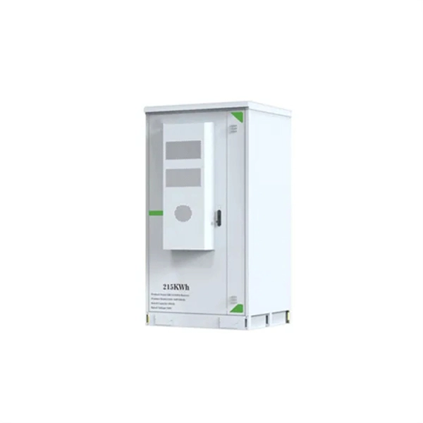
This comprehensive guide is intended to shed light on the various aspects of the PZ30 distribution box, including its design, components, functionality, and installation procedures. The PZ30 lighting distribution box plays a crucial role in this process, providing a centralized hub for managing and protecting electrical circuits in both residential and commercial settings. With modern aesthetics, safety-focused construction, and user-friendly features, it meets the needs of diverse applications. This versatile unit features a robust construction with high-quality thermoplastic materials, offering excellent protection against electrical. The PZ30 distribution box is a specialized electrical enclosure designed for single-pole circuit breakers, offering safe and organized electrical distribution in residential and commercial systems. The box features. This article details the features, installation methods, and user experience of the chint pz series nx household 30a circuit breaker distribution box. One of the key benefits of the PZ30 series is its modular design, which allows for flexible.
[PDF]
The soft starter wiring diagram typically includes information about the power supply, motor connections, control circuit, and bypass arrangement. It helps in understanding the complete wiring arrangement and makes it easier to troubleshoot any potential issues. See Technical Data TD03900001E. We are guided by our commitment to do business right, world's most urgent power management challenges. A proper wiring diagram is crucial to ensure the soft starter functions effectively and protects the motor from any kind of damage. Whether you're a professional electrician or a DIY enthusiast, this detailed wiring diagram and installation guide will help you understand the c. more. Soft starters are widely used to reduce the current surge when devices are started and to provide ramped acceleration to motors. The use of soft starters can reduce energy costs by up to 15%, as well as providing protection from damage caused by voltage sags or electrical faults. Connecting the soft starter to a wye motor inserts the SCRs directly in the line wiring, referred to as "In Line" wiring. If the motor is hard. If you're looking to install a soft start system in your electrical setup, it's crucial to understand the wiring diagram that goes along with it. A soft start system is designed to gradually increase the voltage and torque to a motor, reducing the initial inrush current and protecting both the.
[PDF]
Professional quotes from experienced fiber optic cable installation contractors are crucial for accurate project estimates, as the costs of fiber optic cabling can vary significantly based on location, terrain,.
[PDF]
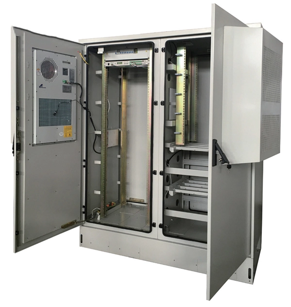
A neat, well-organized subpanel bundles wires to conserve space and improve access. Ideally, wire groups are installed in layers and wires are bent at right angles to buses or breakers. Label short sheathing sections (slugs) to indicate which circuits wires serve. Choose the right box based on environment (indoor/outdoor), load capacity, and durability. Check for proper IP/NEMA ratings and material quality. Ensure safe placement: install in. Welcome to this live training session! ⚡ In today's tutorial, I'll be demonstrating how to arrange cables neatly inside a distribution bo. more See what others said about this video while it was live. Wire color: The neutral wire is blue, and the color of the phase wire (A phase is yellow, B phase is green, and C phase is red). It consists of various protective and control devices for electricity distribution in a building. 📌At the top, there are main circuit breakers and residual current devices (#RCDs), which protect against overcurrent and leakage currents. 📌The middle section includes an electric energy meter that. Wiring distribution panels serve as the central hub and nerve center, routing power from the main service feed to multiple circuits. When setting up such a significant component of industrial, commercial, and utility applications, it's essential to get everything right. When wiring distribution.
[PDF]

This handbook covers the code of practice in protection circuitry including standard lead and device numbers, mode of connections at terminal strips, colour codes in multicore cables, dos and donts in execution. Also principles of various protective relays and schemes including special protection. Read this document and the documents listed in the additional resources section about installation, configuration, and operation of this equipment before you install, configure, operate, or maintain this product. Users are required to familiarize themselves with installation and wiring instructions. presentation of protection and control relaying. The report will identify methodology behind these practices, present issues raised by the integration of microprocessor relays and the internal logic and external communication configurations, ying. The objective of this presentation is to convey a basic understanding of protective relays to an audience of engineers already familiar with low voltage protective device coordination. HT panel protection relay. The HT power supply is received from GO switch and distributed to the. The handbook for protection engineers includes guidelines on protective circuitry, protective relay principles, and testing procedures for switchgear and relays. It covers standard codes, wiring practices, and norms for protecting generators, transformers, and lines, and provides detailed.
[PDF]

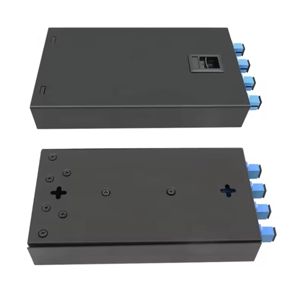
This publication shows how to wire and install the 4010-9825 24V Distribution Block into a 4010 Fire Alarm Control Panel (FACP). Refer to the 842-058 Field Wiring Diagram for additional wiring information. 1 Transformer connection: Two red wires connect to AC 220V input port, while two yellow wires connect to AC input port of main board (had connected by the factory. 2 DC12V battery connection: Red wire on the circuit main board connects to the positive pole of acid-lead battery while black. Notify the carrier and call Telect's Customer Service Department at 1-800-551-4567. Keep the container until you have checked equipment operation. Use the original, undamaged container if you are instructed to return. Learn how to wire a distribution box step by step! This video shows real on-site footage of electrical installation, demonstrating safe and standardized wiring methods used by professionals. Such a system, however, does not assure. Material preparation: Prepare the required circuit breakers, wires, wiring ties and other materials, and ensure that they meet the design drawings and installation requirements. Location determination: Determine the installation position of the circuit breaker according to the position of the.
[PDF]
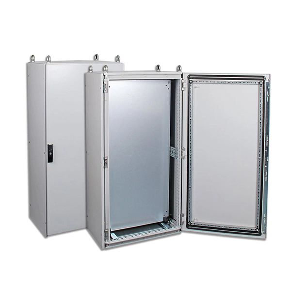
Check for proper IP/NEMA ratings and material quality. Ensure safe placement: install in dry, accessible areas with good ventilation and at appropriate height (typically ~1. Practice good wiring: secure grounding, neat cable management, proper insulation, and correct wire gauge. In this video, we'll walk you through the process of wiring a home distribution box with a detailed connection diagram. Whether you're an electrician or a DIY enthusiast, this guide will help you understand the basics of home electrical distribution. more Welcome to our channel! In this video. However, the key to a safe and reliable system lies in proper installation. If it's done poorly, you risk short circuits, fire hazards, or system failure. Done right, it ensures safety, compliance, and long-lasting performance. In this guide, we'll break down everything you need to know to install. Distribution board is a safe system designed for house or building that included protective devices, isolator switches, circuit breaker and fuses to safely connect the cables and wires to the sub circuits and final sub circuits including their associated Live (Phase) Neutral and Earth conductors. Learn how to wire a single-phase household distribution box in just 60 seconds! In this quick tutorial, we'll cover the essential components and wiring steps for a safe and efficient distribution setup in residential areas.
[PDF]

This guide shows you how to organize circuit breaker wiring properly. You will learn to build a safe, efficient, and professional electrical system today. Circuit breaker wiring configurations involve organizing main switches, busbars, and branch breakers within a distribution box. Messy distribution boxes are dangerous and very hard to fix. It takes the incoming power and safely distributes it to different circuits throughout your building. Whether in a home or an industrial facility, this box keeps your electrical setup organized, functional, and efficient. The distinction between 1P and 2P circuit breakers plays a pivotal role in determining the appropriate protection level for various circuits. Learn how to wire a distribution box step by step! This video shows real on-site footage of electrical installation, demonstrating safe and standardized wiring methods used by professionals. It serves as a central hub for distributing electricity throughout a building, ensuring that power is delivered safely and efficiently to all the required locations. At the heart of a breaker box is the main breaker, which controls the flow of electricity from the utility into the building. From the main breaker, power is sent to individual circuit breakers, each of.
[PDF]
Free electrical calculators for wire sizing, voltage drop, load calculations, conduit fill & power factor. NEC compliant tools for electricians & engineers. In this guide, we'll break down everything you need to know to install a distribution box correctly and confidently. Choose the right box based on environment (indoor/outdoor), load capacity, and durability. Check for proper IP/NEMA ratings and material quality. Ensure safe placement: install in. Professional electrical wire sizing tool based on National Electrical Code (NEC) standards. Calculate proper wire gauge, voltage drop, and ampacity for safe electrical installations. Input your electrical parameters to get accurate wire size. Pro Insight: A well-planned distribution box feels like a silent partner—you only notice it when something's wrong. Our goal? Make sure you never notice it. Before we dive into calculations, let's get familiar with a few essentials: 1. Create accurate bids and win more projects with automated formulas. The sizing requirements for pull boxes, junction boxes, handhole enclosures, and conduit bodies exist to prevent conductor insulation damage. Those requirements are in 314. 28, and they apply to all conductors 4 AWG and larger (Fig. To illustrate how these requirements prevent conductor. Estimate wire ampacity with derating factors for temperature and conduit fill. Reference tool based on NEC guidelines. It is NOT a substitute for professional.
[PDF]
Electrical service line replacement costs $225 to $500 for your project, based on your home's setup and access. Your home's layout and local code set your total wire length, especially from the meter to breaker box. Buyers typically pay for a full panel replacement, including labor, materials, and permits. Key cost drivers include panel amperage, indoor vs outdoor location, wiring length, and whether a full panel upgrade or rerouting is needed. The article outlines cost ranges, per-unit pricing, and practical. Residential electrical repair costs can vary depending on the scope of work, materials needed, labor requirements, and site-specific conditions. Your project needs permits and utility coordination, and underground service lines. The average cost to hire an electrician to install or repair light fixtures, outlets, switches, or fans ranges from $141 to $419 with homeowners spending $280 on average. For larger electrical jobs like installing wiring or replacing an electrical panel, expect to pay $2,000 to $6,000. Get free. Upgrading your home's wiring and electrical panels can bring your home up to code and help you avoid electrical fires and shocks. This process can be expensive, though.
[PDF]
Basic: 100A indoor replacement — Panel, new breakers, basic wiring; 6–8 hours; total $1,200–$2,000; includes standard permit where required. Key cost drivers include panel amperage, indoor vs outdoor location, wiring length, and whether a full panel upgrade or rerouting is needed. The article outlines cost ranges, per-unit pricing, and practical. Typical cost ranges for replacing a distribution box or service panel in the United States vary widely based on panel size, amperage, labor, and whether a full service upgrade is needed. A low-amp subpanel costs from $500 to $1,000 while a 200-amp panel upgrade runs up to $4,000. Total costs depend on the type of home, the number of circuits, and the amperage. Our homes are. Upgrading or installing a residential electrical panel in the San Francisco Bay Area is a significant project that must meet California's stringent safety codes. This article outlines the cost factors, price ranges, and practical budgeting advice for a U. The price depends on electrical code upgrades, permit. Electrical service line replacement costs $225 to $500 for your project, based on your home's setup and access. Your home's layout and local code set your total wire length, especially from the meter to breaker box. Your project needs permits and utility coordination, and underground service lines.
[PDF]
A grid networks consist of an interconnected grid of circuits, energized from several primary feeders through distribution transformers at multiple locations. Grid networks are typically featured in.
[PDF]