
Professional-grade cantilever support arm specifically designed for cable tray installations. Features a welded flat mounting plate construction for secure attachment. Manufactured by nVent CADDY, this sturdy support solution provides reliable cable management infrastructure. 0 are currently in. 15. 41x21mm horizontal support for wall fixing of cable trays, electrical conduits and other heating pipe installations, A/C, fire protection systems, etc. Excellent loading capacity. Robust and secure system. Made of steel, available in various protection systems. Available in widths from 100 to 1000. Cable Support Systems are well designed to provide necessary support for cable trays, cable ladders and trunkings. Cable supports are manufactured according to common standards from high quality raw materials. Requires only one bolt for quick fixing and is used with open face at the top. Two bolt. us-trations without notice. All illustrations, descriptions and technical information included in this document are provided as indications and can cable trays are equivalent. The mechanical and electrical characteristics, tests, certifications, overall quality management, recommendations mentioned.
[PDF]
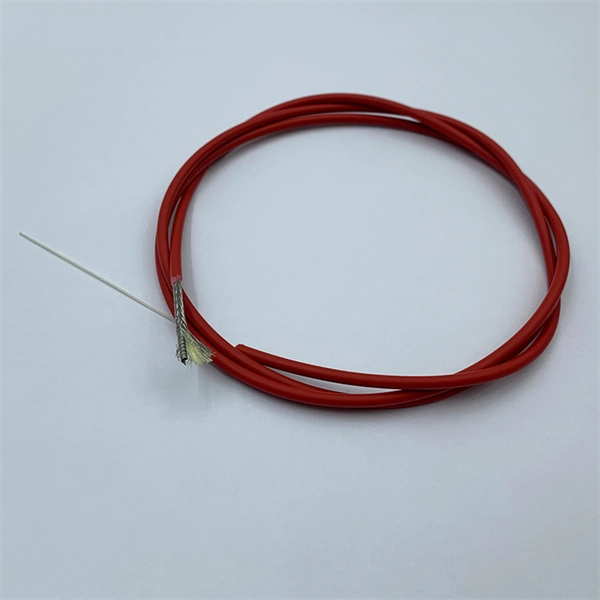
This article will focus on the failure rates of optical modules, analyze the primary causes of failure in traditional Digital Signal Processing (DSP) modules, compare failure rates utilizing LPO technology, and discuss the advantages presented by LPO modules. Linear Pluggable Optics (LPO) are a new optical transceiver technology. The idea is simple: instead of a DSP (digital signal processor) inside the module – replacing it with transimpedance amplifier (TIA) and a driver chip with high linearity and EQ capability – LPO shifts signal processing into. Copyright 2023, Coherent. Next-generation 400G and 800G modules for data centers, AI clusters, and telecoms — validated in a European lab, ready to ship from Europe. What is Low-Power Optical Transceivers (LPO)? Linear Pluggable Optics (LPO) replace the DSP inside the optical module with linear analog components, shifting. QSFP-DD LPO TRANSCEIVER DESIGNED FOR PCIE® GEN 5. 0 over optical link, enabling scalable server disaggregation and efficient rack-to-rack interconnects ideal for AI/ML and. Led by Cisco Optics experts, this MSA quickly gained broad industry support due to its vision to create cost-effective solutions for high-density multi-terabit switching, routing, and transport networks. The goal was to define optical specifications that allow for future 100G and 400G pluggable.
[PDF]

Download new and previously released drivers including support software, bios, utilities, firmware and patches for Intel products. trol I/O is desired. The Q-SYS Core 24f satisfies a broad spectrum of application needs from meeting room environments, conferencing systems, retail establishments, houses of worship, judicial environments, education institutions and other general purpose pro essing applications. A Core 24f may be. That change is why correct leads and connections matter for system stability and lifespan. Please sign in or register for an Intel account. Automatically update your drivers and software Use this tool to identify your products and get driver and. Purpose: This connector serves as the main junction, transmitting essential electrical currents from the supply unit to the motherboard. Design: It features a distinct arrangement of multiple connectors, each designated for specific functions, ensuring balanced and stable power distribution. Product replacement Get replacements and find substitutions for discontinued Schneider Electric products. Where to buy Search our network of verified distributors with over 15,000 sales outlets. Communications bus and supply power terminal blocks, functions, ratings, requirements, and cables provides information about the functions, ratings, and requirements for the communication bus and supply power terminals; and guidelines for wire sizes, cable types, and cable lengths when wiring the.
[PDF]
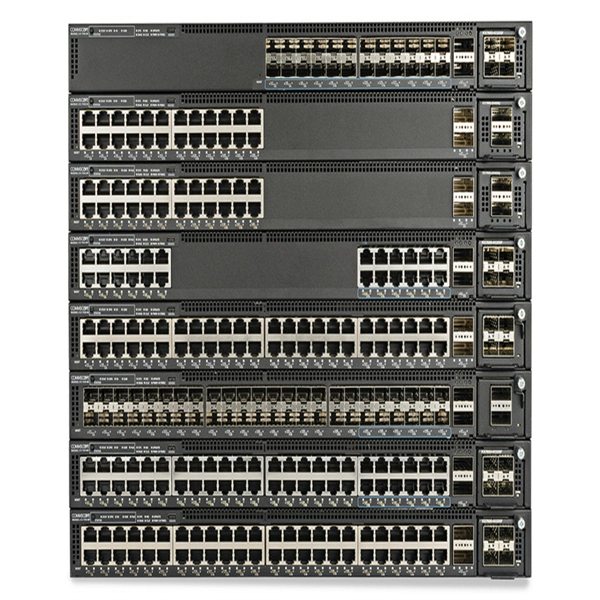
You can connect two Switch consoles via a network in two ways: Wi-Fi or Ethernet cable. For a more stable wired connection, use a Nintendo Ethernet adapter and a category 5e or higher cable. Important: A USB LAN Adapter can be connected to Nintendo Switch Lite using a licensed accessory, such as the Dual USB PlayStand for Nintendo Switch Lite from HORI. Nintendo Switch can connect online with a wireless connection or, when through use of a LAN adapter, a wired connection. Game sharing between two Switch consoles involves setting up your Nintendo. TL;DR: Is there a way to have two different (unreliable) ISPs connected to a single network switch, so that when one drops out, the home network is automatically switched to the other ISP? --- Hi all! I am a networking hobbyist, and I built out a home network for a family friend of mine living in. To view and connect your Nintendo Switch to either the 2. 4 GHz or 5 GHz Wi-Fi band, follow these steps:. 4 GHz and 5 GHz. But before we get into the details, it's essential to understand that the Nintendo Switch supports both 2. 4GHz and 5GHz WiFi frequencies, ensuring faster and more reliable connectivity. Cisco ® Catalyst ® 9200 Series switches extend the power of intent-based networking and Catalyst 9000 hardware and software innovation to a broader set of deployments. With its family pedigree, Catalyst 9200 Series switches offer simplicity without compromise – it is secure, always on, and IT.
[PDF]

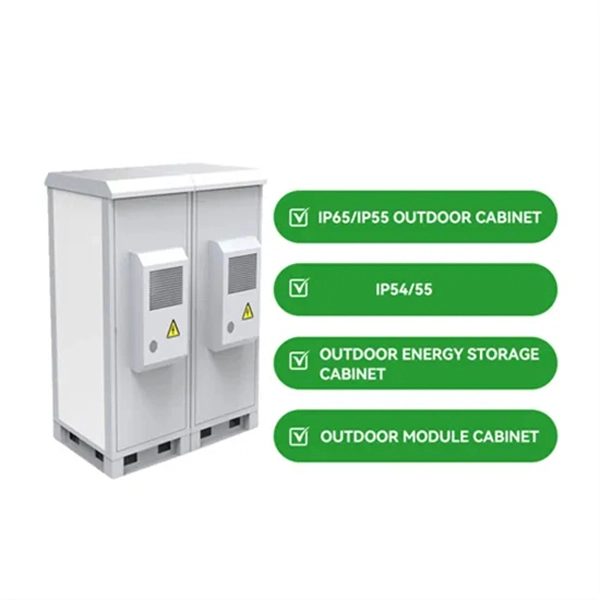
Step-by-step instructions on how to install the Polylok 12" distribution or drainage box. In this guide, we'll break down everything you need to know to install a distribution box correctly and confidently. Choose the right box based on environment (indoor/outdoor), load capacity, and durability. Check for proper IP/NEMA ratings and material quality. Ensure safe placement: install in. The installation of a distribution box is explored in detail, highlighting advanced techniques for achieving a professional and efficient setup. This video provides valuable insights for anyon. more Distribution Box Installation: Advanced Techniques. When it comes to rigid, easy to install electrical box supports, Eaton offers a wide variety of B-Lines series electrical boxes that help reduce installation complexity. For professional installers and property owners, the mechanical components like support rods play a critical role in long-term safety and maintenance efficiency. These components ensure that heavy-duty. Whether you are an electrical contractor or a construction brigade, knowing how to properly and safely install distribution boxes is the basis of ensuring the safe operation of the entire system.
[PDF]

Cable tray support quantity can be calculated using a simple formula: Support Quantity = Total Length ÷ Support Spacing + 1 20 ÷ 2 + 1 = 11 supports In a typical project, a 20-meter cable tray with 2-meter spacing requires 11 supports. Calculating the cable tray support quantity is a crucial part of electrical installation projects. In complex engineering environments, the. Properly sizing your cable tray is critical for safety and compliance. Our free calculator helps you determine the correct tray size based on NEC and IEC standards. This calculator features an interactive interface with advanced visualizations. Open the full calculator for the best experience. Save your cable tray sizing calculator results as branded PDF. Calculate NEC-compliant wire basket cable tray fill, load capacity, and hardware requirements for professional installations. We independently provide precision steel tools, calculators, and expert resources for steel, metalworking, construction, and industrial projects. IEC 61537 covers cable tray and cable ladder systems for the support and accommodation of cables, while NEC Article 392 governs cable. What is the fill capacity and remaining capacity of my cable tray? Calculate cable tray sizing and fill capacity based on tray dimensions, cable diameter, number of cables, and maximum fill percentage per electrical code. Determine whether cables fit within safe fill limits. Cable tray fill.
[PDF]
This guide covers the critical steps, from selecting the right electrical cable tray and performing accurate cable fill calculations to managing a safe cable pull through and ensuring all bonding and grounding requirements are met. Article Summary: A compliant cable tray installation requires a thorough understanding of NEC Article 392, proper structural support, and precise installation techniques. But before you lay the first tray or clamp down a single cable, you need a solid plan. This guide breaks down the process step by step. Here is a step-by-step guide on how to install a standard metal cable tray system (e., ladder or perforated type). Before starting, ensure you have. NEMA VE2 addresses cable tray installation and provides information on maintenance and system modification. NEMA VE2 was developed by the NEMA Cable Tray Section, of which MP Husky is a charter member. Ladder Cable Trays Solid side rail protection and system strength with smooth radius fittings and a wide selection of materials and finishes. Maximum strength for long span applications. Welcome to our step-by-step guide on installing cable trays! In this video, we'll explore the different types of cable trays available and provide detailed instructions for their installation. Whether you're an experienced electrician or a DIY enthusiast, this video is perfect for you.
[PDF]
Cable Management Tray Size: Choose a tray size that will hold the desired amount and length of cable. Support Spacing: Remember the NEC requires no more than 4 feet of support spacing. Bend Radius: The tray cable bend radius should be supported to avoid damaging the cable. Hubbell's NEXTFRAME® Ladder Tray is the effective and widely used cable runway that supports and delivers bundles of cable between cabinets, racks, and closets, along walls, and suspended from ceilings. The Ladder Tray features light, rugged, tubular steel construction. It is designed for. maintain spacing or to keep cables in place when the tray is ect the minimum bend ra-dius for cables as they exit the bottom of the cable tray. Proper installation can significantly reduce electromagnetic interference, prevent fire hazards, and improve overall efficiency. This article provides an in-depth. This publication is intended as a practical guide for the proper and safe* installation of cable ladder systems, cable tray systems, channel support systems and associated supports. Cable ladder systems and cable tray systems shall be manufactured in accordance with BS EN 61537, channel support. Is your cable tray system optimized for safety, dependability, space and cost savings? Cable tray (or cable ladder) systems are a popular alternative to electrical conduit systems, as they have an outstanding record for dependable service, design flexibility and cost savings in commercial and.
[PDF]

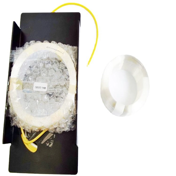
A fiber optic ring network is a physical or logical network topology where devices (usually switches) are connected in a closed-loop using fiber optic cables. Each node is connected to two other nodes, forming a ring-like structure. This design ensures data can travel in both. This guide walks you through everything you need to know about fiber ring networks—from basic concepts to topology diagrams and essential protocols. Instead of running in a straight line from one point to another, the fiber forms a circular pathway linking multiple nodes. The. An example of this is the SONET/SDH (Synchronous Optical Networking/Synchronous Digital Hierarchy) dual-ring architecture, commonly used in telecommunications. A Metro ring refers to a fiber ring that covers a metropolitan area, connecting multiple locations such as data centers, offices, and. A fiber ring is a specialized configuration of a fiber optic network that arranges the physical transmission lines into a closed loop, or a ring. Data travels around this loop from one device to the next until it reaches its destination. It's one of the fundamental ways to organize a local area network, and while it's less. Network reliability and robustness are critical factors for any organization in the digital age. One approach that has proven effective in achieving these goals is using a fibre ring topology by running multiple redundant geographically different fibre paths to the cabinet. Fibre loops, also known.
[PDF]