In an Ethernet patch panel diagram, each port on the patch panel is represented by a numbered or labeled square or circle. The diagram typically includes details such as the port numbers, cable types, and the devices connected to each port. Ethernet patch panel diagram is a visual representation of the connections between Ethernet cables and network devices, such as switches and routers. It provides a clear overview of how the network is structured, allowing network administrators to easily troubleshoot and manage the network. This information can be used to track the location of devices, their serial numbers, and their IP addresses. Change Management: Patch panel connection diagrams can be used to track. A patch panel is an essential component in a network system that provides a central location for connecting multiple devices or cables. The patch panel serves as. A pair of managed Gigabit Ethernet rack-mount switches, connected to the Ethernet ports on a few Panduit patch panels using Category 6 patch cables. (All equipment is installed in a standard 19-inch rack. Each port has a patch connection that links it to another port in another part of your building.
[PDF]
Please view our full RLH price list and contact us at info@fiberopticlink. com if you have any questions or special project needs. A 24-port patch panel is a fundamental component in modern network infrastructure, widely used by IT professionals and network installation service providers. These panels serve as centralized connection points that organize and manage Ethernet or fiber optic cabling within data centers, server. Check each product page for other buying options. Need help? Get reliable 24-port patch panels for voice, data, and video connections. Discover UL-listed options suitable for commercial and professional environments. Among the most widely used configurations is the 24 port fiber patch panel, offering an optimal balance between density and manageability. Love how customizable it is with the ability to add keystone jacks of different types. Free Shipping for many. SNTC-24X7X4 15454 - 2RU 64Ports LC Patch Panel. SP ONSITE 24X7X4.
[PDF]
In this informative video, learn how to seamlessly integrate fiber optic cables with Power over Ethernet (PoE) systems for enhanced connectivity and performance. This installation guide focuses on what a patch panel does, patch panel installation basics, and how to connect patch panel to switch while keeping cabling clean and easy to manage. Switch: What's the Difference? Although a patch panel and a switch can look similar in a rack, they. Fiber patch panels are important components that are used to help organize and protect fiber optic cables. Connecting a fiber patch panel to a switch is a critical step in setting up a fiber optic network. Identify. If the PoE switch has SFP slot built-in, what you need is the SFP module installed in the slot. Firstly, Insert the SFP module into PoE switch's SFP slot. Discover the advantages of using fiber optic cables in conjunction with PoE and gain insights into the necessary components required for. If you have an existing patch panel the short answer to “can I just plug in a cable into the front of it” is yes. In comparison to wiring up individual networks, patch panels are much more efficient and can provide more reliable, faster connections. This article will.
[PDF]
When deploying fiber optics in the field, telecommunications companies need ways to safely and efficiently store and terminate cables. As many technicians know, having the right fiber optic patch and splic.
[PDF]

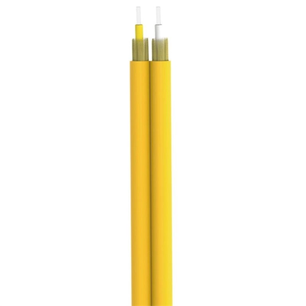
Bend insensitive fiber patch cable is designed to transmit light with minimum loss even if they are bent beyond the bend radius. Fiber optic patch cords are often treated as low-risk consumables, yet a large percentage of optical link failures originate at the patch cord level. Unlike backbone cables, patch cords are frequently connected, disconnected, bent, and handled by technicians, making them the most vulnerable. The bend radius of fiber cables is critical for maintaining high performance and longevity. During installation under tension, maintain a minimum bend radius of 20 times the cable's outer diameter, while post-installation requires a minimum long-term bend radius of 10 times the cable diameter. Fiber optic cables are designed to withstand some bending, but excessive bends can physically damage the glass fiber or cause significant signal loss. That's why every fiber cable has a minimum bend radius specification provided by the manufacturer. The minimum bend radius defines the smallest. When fiber optic cables are bent more sharply than recommended, the internal fibers can break or develop micro-fractures, leading to: Reduced Signal Quality: Noticeable deterioration in signal transmission, including lower speeds and data loss, often results from bending-induced damage. As the bending becomes more acute, more light leaks out (shown in the picture below).
[PDF]
A Main Distribution Board (MDB) is the primary power distribution point in large buildings or industrial systems. It receives electricity from a transformer or main source and sends it to sub-panels or circuits. These panels include main circuit breakers, busbars, and surge protection devices. Ever wondered how electricity from the grid reaches every switch, socket, and appliance in a building—safely and in the right amount? That's. Rated up to 6300A. The Main Distribution Board (MDB) is the primary low-voltage power distribution assembly in a facility, receiving energy from a transformer, generator incomer, or utility service and routing it to MCCs, final. Main distribution board (MDB): a distribution board that fulfills all the functions of a main electrical distribution for the supplied area assigned to it and where the voltage is measured for operating the electric supply system for safety services [defined in the IEC 60364-7-710-2021]. Sub Distribution Board (SDB) 3. Unitized Panel. Look no further than Distribution Board Panels, also known as DB Panels. These essential components are the backbone of any electrical power distribution system, providing a central hub for power distribution and protection against electrical faults. But what exactly are DB Panels, and why are they.
[PDF]

Multi-mode fiber optic patch cords utilize a larger core size, typically around 50-100 microns, allowing them to carry multiple modes of light. This design enables the transmission of data over relatively short distances with high bandwidth capabilities. A fiber-optic patch cord is a fiber-optic cable capped at each end with connectors that allow it to be rapidly and conveniently connected to telecommunication equipment. This is known as interconnect-style cabling. A fiber-optic patch cord is constructed from a core with a high refractive. These short fiber optic cords connect transceivers, switches, patch panels, and servers. Without them, even the best optical modules and switches cannot deliver performance. As data rates increase from 10G → 100G → 400G → 800G, patch cables must handle more bandwidth, more density, and stricter. Fiber optic patch cords, also known as fiber optic patch cables or fiber jumpers, are indispensable components in modern optical networks. They act as the critical link for interconnecting devices like optical switches, servers, and distribution frames. Understanding the various technical. Fiber patch cables, also called fiber-optic patch cords, are cables typically containing one or two optical fibers, which are equipped with standardized fiber connectors on both ends. The function of the fiber patch cord.
[PDF]

A fiber patch panel is a mounted enclosure—either rack-mounted or wall-mounted—used to terminate, manage, and interconnect multiple fiber optic cables. It acts as a hub for organizing splices and patch cords, streamlining fiber management and preserving signal integrity. Cable Organization:. Structured cabling is a standardized system to help you organize and install the cables and hardware that connect your different devices to your network (including computers, servers, cameras, or any other smart gadgets). Structured cabling uses consistent components, such as patch panels, jacks. A fiber distribution panel is also called a fiber patch panel. It helps you keep fiber optic cables neat in your network. You use this device to connect and separate fiber cables. It does not need power to work. Serving as the network's centralized junction, it provides secure ports for both incoming and outgoing. Fiber optical patch panels can help data center management cables. Do you know which types are available? What are their functions? This article will show you. With the development of data centers, the cabling infrastructure is getting larger and larger, the patch panel gives the data center a. A patch panel, including fiber patch panels and Ethernet patch panels, is a passive network device that centralizes, terminates, and organizes multiple copper or fiber cables.
[PDF]

Excavate the cable at the break point and use a fiber optic cutter to remove the damaged section. Use a high-precision fiber cleaver to prepare the fiber ends for splicing. Step1 : Identify the optical cabinet and network operating center, and find the fiber optic splitter. Step 2: Identify the splitter number. Step 4: Find the optical fiber port and cable sequence that leads to the user. 2) The. Here are the steps to patch a fiber cable. Make sure the connectors are free from dust or dirt and that there is no damage to the cable's. When fiber cables sustain damage, specialized repair techniques help restore connectivity and maintain data integrity. This comprehensive guide outlines professional fiber optic repair protocols that align with industry best practices. Adhering to precise methodologies, we can mend impaired cables. Learn how to splice fiber optic cable step by step in this complete guide! In this video, you'll see the full fiber splicing process — from fiber preparation, cleaving, and fusion splicing to final testing. Whether you're a network technician, IT professional, or telecom operator, you'll find practical steps, tools, and tips to restore. By understanding these key elements and following the outlined steps, you can effectively repair fiber optic cables and maintain the high-performance network necessary for today's demanding communication needs. When it comes to ensuring nice network experiences for users, the condition of a fiber.
[PDF]

The primary function of a fiber adapter panel is to provide a housing for fiber optic adapters or connectors. These adapters act as the interface between the terminated fiber ends and the active equipment, such as switches, routers, or servers. A fiber patch panel is a mounted enclosure—either rack-mounted or wall-mounted—used to terminate, manage, and interconnect multiple fiber optic cables. It acts as a hub for organizing splices and patch cords, streamlining fiber management and preserving signal integrity. This guide will focus on elucidating the aspects of the fiber patch panel, its accessories, the work done with such a device, and how to. Fiber optic networks are the backbone of fast, reliable internet and modern communications, but even the best fiber cables need the right connectors and patch panels to work efficiently. Connectors are the points where fiber cables link to devices, equipment, or other cables, and using the right. The fiber optic patch panel, also known as the fiber distribution panel, serves as the crucial component of the management of fiber optic cables. Also, the advantage of fiber optic patch panels is to reduce the loss of fiber optic transmission and facilitate engineers to troubleshoot. Serving as the network's centralized junction, it provides secure ports for both incoming and outgoing fibers, streamlining connection.
[PDF]
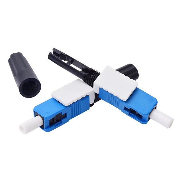
The optical fiber cable and the cable are the same, the difference is located in the fiber patch cord without the network shielding layer, and the center is the optical fiber glass core. The glass envelope surrounds the core, followed by a thin plastic jacket on the outside. The main components of. Of the more than a dozen types of fibre-optic connectors available, the four most commonly used today are LC, SC, FC, and ST. In addition to serving the same general function, the four connectors differ in size, locking mechanism, and best applications. The following guide systematically describes. A fiber optic connector is a mechanical device that allows two fibers to be joined precisely, enabling light to pass with minimal insertion loss and reflection. A good connector: Provides low insertion loss (minimal signal attenuation). They directly affect insertion loss, return loss, reliability, and long-term network stability. The ferrule diameter of the SC connector is 2. There is a spring inside the flange and if you hear the springs twanged when you insert the connector into the flange, that means the. Whether back in the late 1990s or today, you will see 8P8C RJ45 type connectors at the end of Ethernet patch cords and keystone jacks mounted in walls running back to patch panels. The T568A and T568B color code has remained the same too, dictating the wiring color code sequence to make proper.
[PDF]
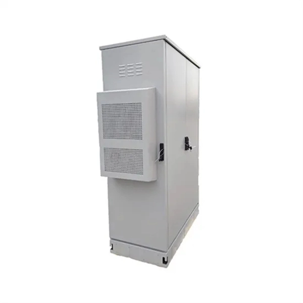
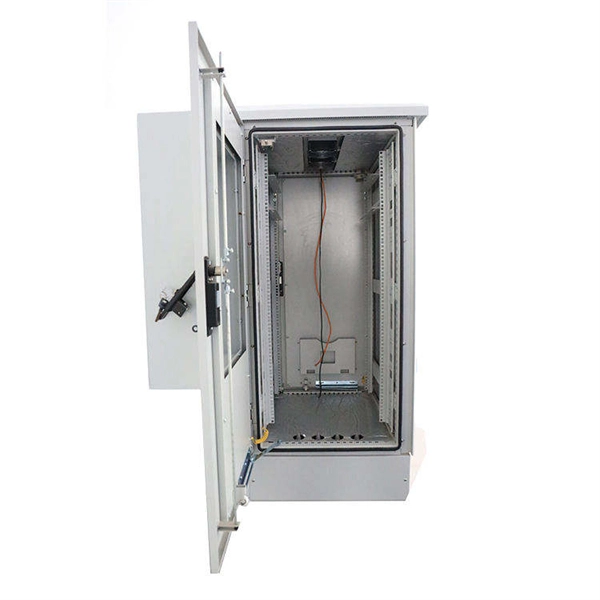
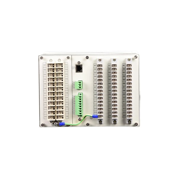
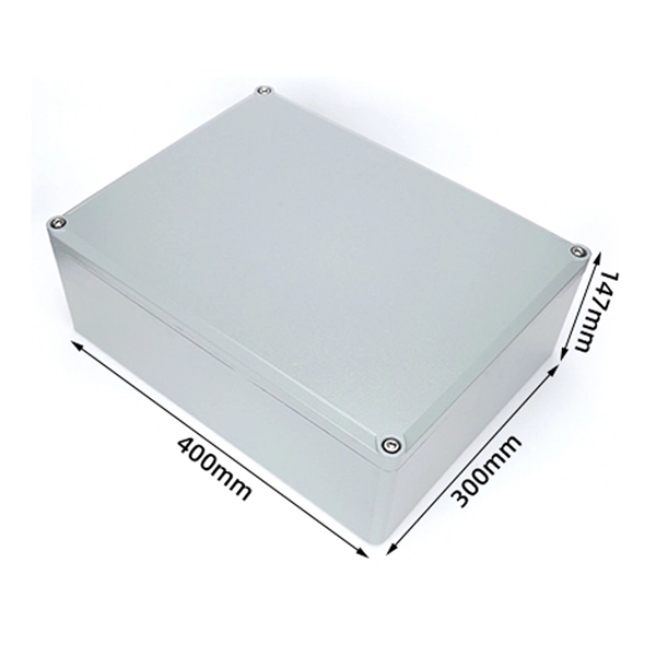
Buy low price 4 Cores Ftth Mini Fiber Optic Terminal Box/patch Panel Gz-idp-a4 by Shanghai Huijue Network Communication Equipment Co., a leading supplier from China. 2848 similar products are also available from global exporters. Capacity: 576 Cores Max. Huijue FTTH Fiber Optic PLC Splitter SC UPC/APC Connector 1x2 1x4 1x8 1x16 White Black Grey 1 Pcs /box 8. Get exactly what you're looking for. Optical fiber active connectors: Optical patch cords, optical fiber connectors, optical fiber patch cords, Optical splitter: Optical fiber coupler, optical splitter, fused coupler, fused taper, planar waveguide optical splitter, plc splitter, coupler, blade type, box type, rack type, lgx, Fiber. 1. IP66 EMC protection 2. United State military standard 3. ISO 9001:2000 OUTDOOR CABINET Summary:J-NET-XF6 series outdoor telecommunication cabinet is maily used in the field of traffic, CATV, electric power etc., Ltd (HJ Network for short) is the leading manufacturer and solution provider for telecom and communication products. The headquarter of HJ Network including the R&D center, technical center, prototype dept and sales is.
[PDF]
Single mode fiber patch cord: Single mode 9/125um optic patch cord are designed for long-distance transmission. They have a smaller core diameter (typically 9 microns) compared to multimodeoptic.
[PDF]

A Mode Conditioning Patch Cord (MCPC) is a specialized fiber patch cord designed to control the launch condition of light from a single-mode transmitter into a multimode fiber. Fiber optic cables primarily come in two types: Multimode Fiber (MMF): Has a larger core, allowing multiple light modes (paths) to travel. It's designed for short-distance, high-bandwidth applications within buildings or campuses. Common types are OM1, OM2, OM3, and OM4. Its primary purpose is to reduce differential mode delay (DMD) and prevent bandwidth limitation when legacy multimode. FS offers OM1 & OM2 mode conditioning fiber optic patch cables (MCP) in any connector & cable length, optimal for eliminating differential mode delay effects. This document describes the installation and use of the mode-conditioning patch cords listed in Table 1. 3z-compliant optical fiber assembly consisting of a single-mode fiber permanently coupled off-center to a 62. 5/125) fiber optic cable by offsetting the Singlemode Laser launch from the.
[PDF]

In this tutorial by TiFi Design, you'll learn in-depth how to create. In this tutorial by TiFi Design, you'll learn in-depth how to create. In this geometry nodes tutorial, learn how to design procedural fiber optics in Blender! You'll learn in-depth how to create, distribute, and reshape splines; capture attributes; and use those attributes to build a vibrant shader. more In this geometry nodes tutorial, learn how to design. Building Information Modeling (BIM) uses multi-dimensional, spatial models that incorporate detailed product information for the building components. Blender enthusiast and YouTuber, I make video. Just wanted to share my recent geometry nodes tutorial on how to design brilliant fiber optics. I hope you enjoy it! https://youtu. be/l-OGJml_sRQ The largest. When communicating between systems, either via the internet or via an internal network system, a medium needs to be in a place that can facilitate the transmission of data, both sending and receiving. There are numerous options available for laying down communication mediums, such as coaxial cable. The Computer-Aided Design ("CAD") files and all associated content posted to this website are created, uploaded, managed and owned by third-party users. Each CAD and any associated text, image or data is in no way sponsored by or affiliated with any company, organization or real-world item.
[PDF]