Optical return loss is the amount of light that is reflected back to the source, this reflected light is measured at each connector and splice at each point over the entire fiber link. This is always measured in dB (decibels) and will be displayed as a negative number. The closer the number is to. The polish of a singlemode fiber endface plays a significant role in reflectance. Understand what you need before you specify. The Institute of Electrical and Building the ORL story Electronics Engineers (IEEE) recently Within a fiber-optic channel or path-released new specifications within way. Optical Return Loss (ORL) in fiber optics refers to the amount of light that is reflected back toward the source in a fiber link. ORL is usually expressed in decibels (dB) as a positive value, with. Return loss (RL) is also called reflection loss. When high-speed signals enter or exit a part of an optical fiber, such as an optical fiber connector, discontinuity and impedance mismatch may cause reflection, which is the return loss of an optical fiber. Poor ORL is commonly caused by dirty connectors, poor splices, mismatched connector types, or damaged fibers. ORL is measured using ORL meters. Home Coherent Optics Optical Return Loss (ORL) Explained Comprehensive Guide to Understanding and Managing Back-Reflections in Fiber Optic Systems What is Optical Return Loss (ORL)? Optical Return Loss (ORL) is a critical parameter in fiber optic systems that quantifies the amount of light.
[PDF]

GOOD WILL INSTRUMENT (SUZHOU) CO. Browse online or download User Manual for Equipment Gw-instek GOS-652G. GW Instek GOS-652G User Manual 50MHz Cursor Readout With Delayed Sweep.. GOS-658G 20MHz Cursor Readout... GOS-652G 35MHz. Caution statements identify conditions or practices that could result in damage to this product or other property. THIS APPLIANCE MUST BE the letter E or by the earth symbol or coloured Green or Green & Yellow. EARTHED The wire which is coloured Blue must be connected to the terminal which is. y have a fraction of the total loss compared to fiber-based equivalents. FBG also provides a latency in the o der of nanoseconds as compared to microseconds in fiber-based solutions. The FBG based DCMs are designed to perfectly mimi the dispersion and dispersion slope characteristic of G. 652 fiber. g sensitivity and low water-peak level. Together they allow unlimited use of the whole telecom wavelength win ow for a great variety of applications.. GOS-653G Basic... GOS-622G. The GOS-653G/652G Series is an example of classic analog oscilloscope design. The GOS-653G /652G cover a broad range of industry applications, such as product design, assembly lines, repair & servicing, and educational purposes for EE laboratories and class experiments. Coupled with various trigger.
[PDF]

The typical specification range of return loss of a fiber connector is -15 dB to -60 dB. Return loss is also known as reflection loss. It indicates the amount of signal reflected back to the transmitting end. Return loss refers to the power loss caused by the reflection of part of the signal back to the signal source during transmission due to the discontinuity of the transmission. Insertion loss, also known as attenuation, is the loss of optical power that occurs when light passes through a fiber optic connector. It is caused by factors such as misalignment, air gaps, and imperfections in the connector components. The lower the insertion loss, the better the performance of. Reflectance (which has also been called "back reflection" or optical return loss) of a connection is the amount of light that is reflected back up the fiber toward the source by light reflections off the interface of the polished end surface of the mated connectors and air. It is also called. Insertion Loss (IL) is the amount of optical power lost as the signal travels from one point to another in a fiber optic link, usually across connectors or splices. Formula for. In optical fiber communication, insertion loss and return loss are two important parameters to evaluate the quality of interfaces between some optical fiber components, such as optical fiber connector, fiber patch cable, pigtail fiber, etc. While it's natural to have.
[PDF]

The max insertion loss of a fiber patch cable is 0. 75 dB (the maximum acceptable value) in the TIA standard. Insertion loss (IL) and return loss (RL) are key performance indicators of fiber optic patch cords. This article explains their concepts, standards, testing methods, and FiberMania's quality assurance workflow to ensure optimal network performance. Fiber optic patch cords are crucial components in. A: Fiber optic loss refers to the reduction in signal strength as it travels through the fiber optic cable. This can be due to various factors, including attenuation, connectors, and splices. Q: How is fiber optic loss measured? A: Fiber optic loss is typically measured using an Optical Loss Test. The estimate, called a "loss budget" is calculated using typical component losses for each part of the cable plant - the fiber, splices and/or connectors. If the measured loss exceed the calculated loss by a significant amount (remembering the inherent uncertainty in all measurements), the system. Insertion loss is usually shortened to IL, and the unit of measurement for insertion loss is dBm. ) in transmission systems. It is the power attenuation of the signal after. At TARLUZ, we specialize in manufacturing high-performance fiber optic patch cords that comply with global industry standards, ensuring optimal signal integrity and long-term stability.
[PDF]

FiberMall MPO16 APC Y Splitter Cables 10m are designed for 800G QSFP-DD/OSFP DR8/OSFP XDR8 optics direct connection and support 800G transmission for Hyperscale Data Centers. Multimode PLC Splitter is a passive optical device used to split incoming signals into two or more output signals. They're capable of operating over a broad wavelength range from 650 nm to 1350 nm (Typ. 650nm, 850nm and 1300/1310nm). 5/125 (OM1, OM2, OM3 and. High-Quality Construction: This Fiber Optic PLC Splitter is manufactured by UT-KING, a reputable brand known for its reliable products, ensuring a durable and long-lasting performance. Optimized for FTTH Solutions: Designed for use in Fiber-to-the-Home (FTTH) applications, this 1x2 OM3 PLC Splitter. Optical coupler is an optical device that combines or splits power from optical fibers. Note: All insertion loss and insertion loss referenced without connectors. Takfly, established in 2000, has been manufacturing. Optional split ration 1:99, 2:98, 5:95, 10:90, 20:80. USource OM3 Fiber Coupler is a 1x2 or 1x3 passvie optical multimode splitter based on FBT (Fused Biconic Taper) technology, packaged in mini ABS box module or steel tube, split into different rations 1:99, 2:98, 50:50, 10:90, 20:80.
[PDF]

5 dB depending on splitter type. Common planning value: 0. Optional: patch panels, attenuators, or extra components. Helps cover dirt, aging, and measurement tolerances. Adds Rx power and margin calculation. Calculate insertion loss for passive optical splitters in PON and distribution networks. Power is divided equally among output ports. Excess loss accounts for manufacturing imperfections, typically 0. DISCLAIMER: These calculators are provided for. Optical splitters, encompassing FBT (Fused Biconical Taper) couplers and PLC (Planar Lightwave Circuit) splitters, are prevalent passive optical devices designed to divide fiber optic light into multiple segments based on a specified ratio. Fiber optic splitters are vital components within. In fiber optic networks, particularly in FTTx (Fiber to the x) and PON (Passive Optical Networks) deployments, splitters play a central role in distributing the optical signal from a single source to multiple destinations. Optional: patch. Understanding optical splitter loss isn't just about plugging numbers into a calculator. It's about knowing what factors contribute to that loss, how manufacturers specify it, and how it impacts the overall performance and reach of your network. Understanding the types of splitters, their impact on network performance, and how to measure their losses ensures high-quality network operation and facilitates optimal splitter selection based on.
[PDF]

5 dB depending on splitter type. Common planning value: 0. Optional: patch panels, attenuators, or extra components. Helps cover dirt, aging, and measurement tolerances. Adds Rx power and margin calculation. Use 2×N when two inputs feed the same distribution stage. Wavelength is recorded in outputs for documentation. Optional: patch. FTTH / PON Splitter Loss Calculator - Zion Communication is a professional manufacturer of cables and accessories for signal and low voltage transmission. Estimate whether an FTTH or PON optical link is feasible by calculating PLC splitter loss, fiber attenuation, connector loss, splice loss and. In fiber optic networks, particularly in FTTx (Fiber to the x) and PON (Passive Optical Networks) deployments, splitters play a central role in distributing the optical signal from a single source to multiple destinations. These are known as passive optical splitters, and they perform the function. The formula for the theoretical loss for each output port of a splitter with N output ports is: Theoretical Split Loss (in dB) = 10 * log10 (N) Where: N is the number of output ports the splitter has (e., 2 for a 1x2 splitter, 4 for a 1x4, 8 for a 1x8, 32 for a 1x32, etc. Passive split links usually lose the most dB at the splitter, so we keep the optical budget and the installed route separate. These are especially important for FTTH (Fiber to the Home), data centers, and Passive Optical Networks (PON), where.
[PDF]

Download the list of Fiber Optic Products Suppliers in Western Asia as of May 05, 2025 with and without website information. 25% increase from 2023. 10% of all Fiber Optic Products Suppliers in Western Asia are single-owner operations, while the remaining 7 which. Here are the top-ranked fiber optic connector companies as of May, 2026: 1. Thermalogic Corporation, 2. These. Fiber Optic Connectors are an essential component of any fiber optic network that provides a secure and reliable connection between two fiber optic cables. The leading manufacturers of Fiber optic connectors are listed below. Narrow down on the list of companies based on their location and. AFL, based in Duncan, South Carolina, is a prominent manufacturer of fiber optic products and solutions. Established in 1984, the company has built a reputation for delivering high-quality products that cater to the telecommunications and industrial sectors. AFL's extensive product line includes. UnitekFiber produces high quality of MPO|MTP Cables, Fiber Optic Patchcords, SFP Optical Transceivers, MPO|MTP Patch Panels and Outdoor Fiber Cables. We design, create and deliver reliable and cost effective fiber optic products to meet customers' business goals. Our international database.
[PDF]
Pricing (USD) Filter the results in the table by unit price based on your quantity. A tariff of 8% may be applied if shipping to the United States. SHENZHEN FORMAN PRECISION INDUSTRY CO. ZHEJIANG JINGHONG ELECTRIC CO. Bus bar connectors are critical components in electrical power distribution systems, providing secure, low-resistance connections between bus bars and other conductors such as cables and circuit breakers. A. The global bus bar connector market is experiencing steady growth, driven by rising demand in industrial automation, renewable energy, and electric vehicle (EV) manufacturing. According to a 2023 report by Grand View Research, the market size reached $12. 4 billion in 2022 and is projected to grow. In what shapes, busbars are manufactured? Busbars are manufactured in metallic strip, rods and solid bars. The rods can be solid or hollow inside. What are the most suitable metals for busbars? For manufacturing busbars, copper and aluminium are the most preferred metals.
[PDF]

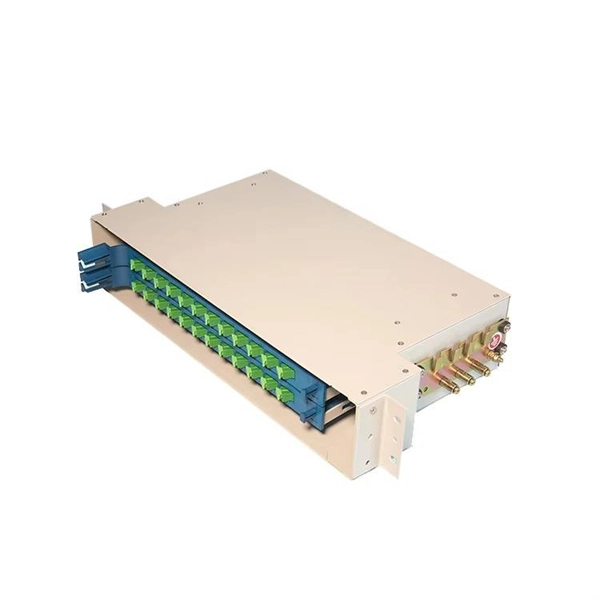
The primary function of a fiber adapter panel is to provide a housing for fiber optic adapters or connectors. These adapters act as the interface between the terminated fiber ends and the active equipment, such as switches, routers, or servers. A fiber patch panel is a mounted enclosure—either rack-mounted or wall-mounted—used to terminate, manage, and interconnect multiple fiber optic cables. It acts as a hub for organizing splices and patch cords, streamlining fiber management and preserving signal integrity. This guide will focus on elucidating the aspects of the fiber patch panel, its accessories, the work done with such a device, and how to. Fiber optic networks are the backbone of fast, reliable internet and modern communications, but even the best fiber cables need the right connectors and patch panels to work efficiently. Connectors are the points where fiber cables link to devices, equipment, or other cables, and using the right. The fiber optic patch panel, also known as the fiber distribution panel, serves as the crucial component of the management of fiber optic cables. Also, the advantage of fiber optic patch panels is to reduce the loss of fiber optic transmission and facilitate engineers to troubleshoot. Serving as the network's centralized junction, it provides secure ports for both incoming and outgoing fibers, streamlining connection.
[PDF]
There are several diagnostic methods to help troubleshoot fiber optic connectors, and the diagnostic method is to cross-section the fiber optic connector. This technology allows us to actually look inside the fiber optic connector to see defects and pinpoint the cause of. Fiber design and transmission technology have collaboratively evolved to increase bandwidth. Dig-ups dominate! Cablers have very little influence on the majority of causes of cable field failures. While a small percentage, we can examine the “intrinsic” cable failures and what is done to prevent. Connector failure is most frequently the result of a dirty or damaged end-face. Fiber-optic connector: SC type In the connector, the element that holds the fiber and provides the alignment positioning is the ferrule. The. In August of 1999, Boeing Corporation (Boeing) engineers being used on International Space Station flight a defect in the glass fiber (see Figure 1, “Rocket and NASA engineers and managers, Boeing created and reliability of the cable installed in the U. Fiber coupling can be accomplished by fusion splicing.
[PDF]
Mechanical Transfer-Registered Jack (MTRJ) connectors are duplex connectors developed by AMP/Tyco and Corning. They use pins for alignment and come in both male and female guises. It has a plastic bod.
[PDF]
The Asia-Pacific fiber optic connector in telecom market is analyzed and market size insights and trends are provided by country, product type and cable type as referenced above. The countries covered in the.
[PDF]
Here's a quick guide to make sure your fiber optics sail through the cold season: While fiber optics are tough, cold temps can cause trouble. Water in cables can freeze, potentially harming connections. Ensure tight seals on cable joints and connectors to. The fiber carries data as pulses of light, and has nowadays overtaken copper wire as the medium of choice – primarily because it is lower cost, faster and less bulky. Optical fiber is also harder to hack than copper, making it more secure and safer because it doesn't generate heat. There is. Fiber optic cables are the backbone of modern high-speed data transmission, offering unparalleled speed and reliability compared to traditional copper wires. Summary : Winter weather generally has minimal impact on fiber optic cables since they transmit data through light rather than electricity, making them resistant to temperature-related signal loss. Waterproofing prevents icy.
[PDF]
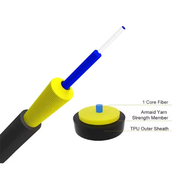
GYTS is a model designator for outdoor fiber optic cable. 'G' indicates it's for outdoor use, 'Y' for its Polyethylene (PE) sheath, 'T' for the gel-filled loose Tube structure, and 'S' for the corrugated Steel tape ar.
[PDF]