Join Jake from Omnitron in this comprehensive tutorial. Understand the nuances of single-mode and multimode fibers, and how to bridge the gap using media converters. Enhance your tech knowledge and. But what happens when you need to connect an existing multi-mode campus network to a new single-mode service provider link? You can't just splice them together. This is where fiber conversion comes in. This guide will break down the professional methods to achieve seamless single-mode to multi-mode. Single-mode (SMF) and multi-mode fiber (MMF) use different core sizes, sources and wavelengths. These differences determine which transceivers work with which fiber and how far signals can travel. Let's analyze the differences between multimode and single-mode fiber to understand why networks require fiber mode conversion and. How can we convert the multimode to a singlemode fiber system? This complete guide will provide answers to these questions. That is because SMF and MMF have. There are two main types of fiber optic cables: single mode and multimode. Although they can do the same job in some instances, the different construction methods make each of them better suited to certain tasks and budgets. What if end B is located in another building, dozens of kilometers far away from end A? Or end B equipment is single-mode or must use a single-mode fiber connection? In the former case, you.
[PDF]

The goal is to fuse the two fibers together in such a way that light passing through the fibers is not scattered or reflected back by the splice, and so that the splice and the region surrounding it are almost as strong as the intact fiber. Fusion splicing is the process of fusing or welding two fibers together usually by an electric arc. Fusion splicing is the most widely used method of splicing as it provides for the lowest loss and least reflectance, as well as providing the strongest and most reliable joint between two fibers. Fiber Stripping: Selecting Precise Tools and Techniques Selecting the appropriate stripper will depend on the fiber coating diameter. This will typically be 250µm for bare fibers and 900µm for coated fibers. Reputable companies like Jonard, Fujikura, and INNO provide multi-hole strippers calibrated. Fiber misalignment and fiber geometry mismatch (e., core size, core-to-clad concentricity, core and cladding non-circularity, numerical aperture, etc. ) can result in real power loss across a splice joint. However, differences in the backscattering coefficients between two fibers can also show up. Fiber splicing means joining two optical fibers (permanently or temporarily) such that light guided in one fiber and reaching the joint (splice) can be transferred into the second fiber with low insertion loss.
[PDF]

This guide aims to provide a concise understanding of multimode fiber optic cable and its applications. We will explore its characteristics, advantages, specifications, and real-world uses. Multimode fiber (MMF) is an optical fiber designed to carry multiple light propagation paths—or modes—simultaneously. This is made possible by its relatively large core diameter, typically 50 or 62. 5 microns, compared to the ~9-micron core in single-mode fiber. The wider core accepts light from. Multimode fiber optic cables are essential in modern data communication systems since they can transmit data efficiently and at high speeds over short and medium distances. We will explore its. They consist of a transmitter on one end of a fiber and a receiver on the other end. Most systems operate by transmitting in one direction on one fiber and in the reverse direction on another fiber for full duplex operation. Most systems use a "transceiver" which includes both transmission and. Multi-mode optical fiber is a type of optical fiber mostly used for communication over short distances, such as within a building or on a campus. Multi-mode links can be used for data rates up to 800 Gbit/s.
[PDF]
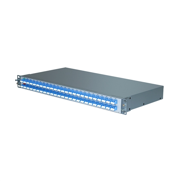
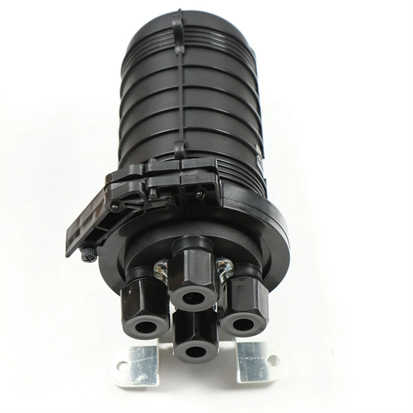
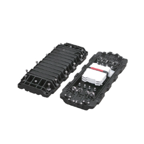
It integrates fiber splicing, splitting, distribution, storage, and cable connection into one unit, providing solid protection and efficient management for building reliable FTTX networks. Total Enclosed Structure: Ensures maximum protection. This fiber optic distribution box serves as a termination point for feeder cables to connect with drop cables in FTTX communication network systems. It is. An optical distribution frame (ODF) is a frame used to provide cable interconnections between communication facilities, which can integrate fiber splicing, fiber termination, fiber optic adapters & connectors and cable connections together in a single unit. It can also work as a protective device. A Fiber Optic Termination Box is a small enclosure located at the terminal end of the fiber where it enters your customer premises. Its function is primarily to splice, secure, and protect the optical fibers connecting the incoming drop cable to the pigtail or patch cable. We separate these products into multiple groups based on application to meet your specifications for mount location and termination capacity.
[PDF]

The fusion method fuses the fiber cores together with less attenuation. Fusion splicing stands out as a superior technique for joining optical fibers, offering a seamless, low-loss connection that is crucial for reliable fiber optic networks. Thorlabs offers a varied selection of single mode (SM), polarization-maintaining (PM), multimode (MM), and double-clad fiber couplers, as well as 1x8 and 1x16 SM PLC splitters; 1x4, 1x8, and 1x16 PM PLC splitters; wideband multimode circulators; RGB combiners; and WDMs. Our SM and double-clad fiber. Castor's Multimode Fiber Splitters (MFS) are designed to efficiently split or combine multimode signals with minimal insertion loss. Manufactured with step-index fibers with core diameter ranging from 50 to 400 µm, they offer uniform splitting ratios across output channels. This method provides a simple, rugged, and compact method of splitting and combining optical signals. Let's explore the fundamentals of mechanical and fusion. A fiber optical coupler (splitter/combiner) route signals to their appropriate destination by splitting, combining or tapping optical signals/channels in a fiber transmission link. Employing a unique fiber fusing process, Lfiber is now able to fabricate and offer a wide variety of fiber optic. Fused couplers are ideal components to split or combine light signals between two fibers over a wide wavelength and temperature range.
[PDF]
Single mode fiber patch cord: Single mode 9/125um optic patch cord are designed for long-distance transmission. They have a smaller core diameter (typically 9 microns) compared to multimodeoptic.
[PDF]

Not all splitters are created equal. Here are the main types you'll encounter: The "1×N" notation indicates one input fiber and N output fibers. A 1×2 splitter divides the signal into two outputs, while a 1×8 splitter divides it into eight. The more splits, the. By dividing a single optical signal from a central Optical Line Terminal (OLT) into multiple outputs for Optical Network Terminals (ONTs) at users' homes, splitters eliminate the need for dedicated fibers to each residence—slashing infrastructure costs while scaling network reach. This guide. A fiber-optic splitter, also known as a beam splitter, is based on a quartz substrate of an integrated waveguide optical power distribution device, similar to a coaxial cable transmission system. The optical network system uses an optical signal coupled to the branch distribution. The fiber optic. Optical couplers can split or join signals in fibers. You can connect many users to one port with 1:n or 2:n splitters. These devices work both ways, which helps strong network communication. In a Passive Optical Network (PON), a single optical fiber carries massive amounts of data using light. They are named by the number of inputs and outputs, so a splitter with one input and 2 outputs is a 1X2, and a PON splitter with one input and 32 outputs is a 1X32.
[PDF]
Single mode and multimode fiber optic cables are two different types of fiber optic cable aimed at different use cases. Single mode cables are typically made with a single strand of glass at their core, leading to a n.
[PDF]

Multimode fibers (MMFs) have recently emerged as an ultimate endoscopic technology that enables high-resolution imaging at the tip of a hair-thin flexible probe. 1,2 A wide range of imaging modalities through MMF-based endoscopes have been demonstrated, including. Holographic wavefront manipulation enables converting hair-thin multimode optical fibers into minimally invasive lensless imaging instruments conveying much higher information densities than conventional endoscopes. Their most prominent applications focus on accessing delicate environments. We experimentally isolate and directly observe multimode solitons in few-mode graded-index fiber. By varying the input energy and modal composition of the launched pulse, we observe a continuous variation of multimode. Monitoring polarization dynamics in multimode fibers is critical for a range of applications, spanning from optical communication to sensing. We begin by introducing the basic concepts such as the spatial modes supported by a multimode fiber and the coupled mode equations for describing the. A multimode fiber stands out as a desirable platform for imaging. Here, we propose and experimentally demonstrate a non-interferometric non-iterative approach for high-speed high-resolution label-free quantitative phase imaging via a random light scattering in a multimode fiber.
[PDF]

A8: Yes, multimode fiber optic cable can support high-speed data transmission depending on the fiber type and network equipment used. Multimode fiber (MMF) is an optical fiber designed to carry multiple light propagation paths—or modes—simultaneously. This is made possible by its relatively large core diameter, typically 50 or 62. 5 microns, compared to the ~9-micron core in single-mode fiber. The wider core accepts light from. Multi-mode optical fiber is a type of optical fiber mostly used for communication over short distances, such as within a building or on a campus. Multi-mode links can be used for data rates up to 800 Gbit/s. Multi-mode fiber has a fairly large core diameter that enables multiple light modes to be. In the realm of telecommunications and networking, multimode fiber optic cable plays a crucial role in efficiently transmitting data over short to medium distances. This guide aims to provide a concise understanding of multimode fiber optic cable and its applications. These fiber cables are structurally designed to transmit several light signals simultaneously, each of which is directed. Unlike copper cables, which rely on electrical signals, fiber optics use pulses of light to transmit data—offering unmatched bandwidth, low interference, and long-distance capabilities. But not all fiber cables are created equal: multimode (MM) and single mode (SM) fibers are the two primary types.
[PDF]

Since the earliest days of fiber optics, multimode cables have typically been color‑coded orange, black, or gray, while single‑mode cables are marked in yellow. For example, cable jacket color typically defines the fiber type, and can differ based on mode and performance level. These colors are typically chosen by industry standards bodies. However, there are some non-standardized colors and inconsistencies that you should be aware of. However, with the introduction of metallic connectors like FC and ST—whose bodies are difficult to color‑code—colored strain relief boots. Multimode fiber (MMF) is a kind of optical fiber mostly used in communication over short distances, for example, inside a building or for the campus. Multimode fiber optic cable has a larger core, typically 50 or 62. 5 microns that enables multiple light modes to be propagated. Because of this, more. Originally developed by the Electronic Industries Alliance (EIA) and the Telecommunications Industry Association (TIA), the TIA-598-D standard (formerly EIA/TIA-598) remains the most recognized color-coding system for optical fibers worldwide. On the right, the yellow patchcord indicates singlemode fiber and the blue connector means it is a regular PC polished connector, If it were an APC connector, it would be green. Perhaps nothing is.
[PDF]

This guide delves into the structure and working principle of fiber optic connectors and outlines the critical steps for creating a successful connection. Proper connection of fiber optic cables is essential to harness these benefits fully, as even minor errors can lead to significant performance issues like signal loss. This article will guide you through the necessary tools, materials, and methods on how to connect fiber optic cables effectively. This guide will explain the entire set of activities involved in installing Fiber optic cable contractors -from the early planning stage right through testing-for facility managers, IT teams, and low-voltage contractors to build high-performance networks safely and efficiently. The processes. However, working with fiber requires specialized skills and equipment to connect cables properly. This guide will walk you through the complete process of connecting fiber optic cable. Before connecting any fiber cable, you need to assemble the proper preparation tools: With the right tools in. The Fiber Optic Association, Inc. (FOA) was founded in 1995 to help develop the workforce to build the fiber optic networks to support a rapid expansion in communications and the Internet.
[PDF]
Connect the fiber optic cable: Attach the fiber optic cable's connector to the transceiver module on the switch. Make sure the connector type (e., SC, LC) matches the transceiver module. Fiber optic cabling is increasingly used to connect network switches and other datacom equipment, especially in long-distance and mission-critical applications. Fiber provides: Increased internet signal bandwidth. Most modern fiber-enabled network switches require an SFP transceiver module. This document describes how to troubleshoot fiber optic interfaces by addressing some of the fiber optic module and cabling specifications. There are no specific requirements for this document. The information in this document is based on all Catalyst 9000 Series switches. This includes Doppler. Connecting a switch to a fiber optic network involves several steps and requires specific equipment to ensure a successful and efficient connection. If you're looking to learn how to configure fiber optics on a Cisco switch, it's important to first configure the switch settings so it's ready for fiber optics. Fiber optic switches utilize. Other than entry level network switches, most of today's network switches include one or more GiBC (Gigabit Converter) or SFP (Small Form-factor Pluggable) slots. SFP modules insert into these slots and and require two strands of fiber, typically duplex Using multi mode fiber (for runs under 1000.
[PDF]
Remove the outer coating carefully to expose the fiber. Use alcohol wipes to remove dust and debris. Make a precise cut for optimal splicing. Align and fuse the pigtail fiber with the main cable. Apply a heat-shrink sleeve for durability. Use an OTDR or power meter to ensure. However, setting up a fiber optic connection to your router can seem daunting if you're unfamiliar with the process. In this guide, we'll walk you through how to connect a fiber optic cable to a router safely and efficiently. This comprehensive guide combines industry standards with field-tested practices to ensure you achieve a rock-solid. Setting up a fiber internet connection requires understanding key hardware components and following a specific connection sequence to establish your home network. Our Experts are helping user's, who are facing issues with their tech gadgets like Router, Modem and extender. If you. Fiber optic technology has revolutionized internet connectivity, offering faster speeds and more reliable connections than traditional copper cables. Connecting a fiber optic cable to a router might seem daunting at first, but with the right tools and a bit of patience, it's a straightforward. Tecnobits - Router - How to connect a fiber optic cable to the router Hello, Tecnobits! 👋 Connecting fiber optic cables to the router so that your internet flies like a spaceship! 😉 Explore with us on our website! And don't miss our latest news.
[PDF]
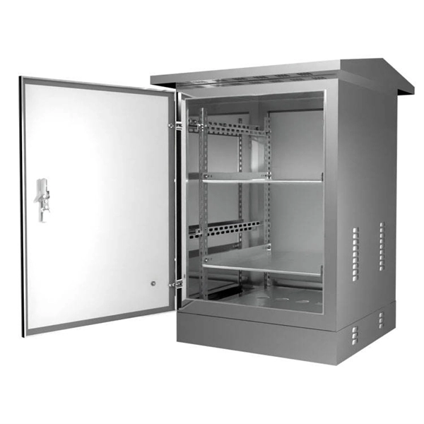
Capable of serving up to 4/8 subscribers, it functions as an essential termination point in FTTx communication networks, accommodating fiber splicing, splitting, and distribution effectively. Elevate your telecommunications infrastructure with the COMX Fiber Distribution Box (FDB), expertly designed for seamless fiber management and distribution. This robust FDB integrates a connectorized splitter, optimizing fiber connectivity and facilitating swift deployment in both indoor and. The FDB-12C Fiber Optic Distribution Box is an outdoor enclosure designed for splicing, splitting, and drop cable connectivity to meet the demands of high-density fiber-to-the-home (FTTH) and fiber-to-the-curb (FTTC) access networks. With capacity for 12 customer connections in a compact IP55 wall. Indoor FTTH Fiber Distribution Box, optical fiber distribution box is used for the fusion splicing, splitting, wiring transmission, and other functions of the optical transmission terminal. It can effectively terminate, protect and manage the optical cable. It is necessary equipment in network. Fiber optic cross connect cabinet, also known as fiber distribution hub (FDH). It play a crucial role in determining the network coverage capacity of a fiber optic network. It provides a structured environment for routing cables, managing splices, and accommodating termination modules. FDBs are used to organize incoming and outgoing cables.
[PDF]