
BER is calculated by comparing the transmitted sequence of bits to the received bits and then counting the number of errors. Whether you're a network engineer validating new inventory or an integrator preparing for deployment, knowing how to test optical transceiver modules can save time, reduce failures, and ensure SLA compliance. Unchecked optical modules can cause: Testing ensures compliance with IEEE 802. 3 and MSA. Bit Error Rate (BER) is a measure of telecommunication signal integrity based on the quantity or percentage of transmitted bits that are received incorrectly. Essentially, the more incorrect bits, the greater the impact on signal quality. It is defined as the ratio of the number of bits received in error to the total number of bits transmitted. It quantifies the error frequency caused by disturbances like statistical noise. What causes bit errors in optical data transmission? In optical systems, bit errors are. One of the most important ways to determine the quality of a digital transmission system is to measure its Bit Error Ratio (BER). Through the interpretation of actual test reports, it.
[PDF]

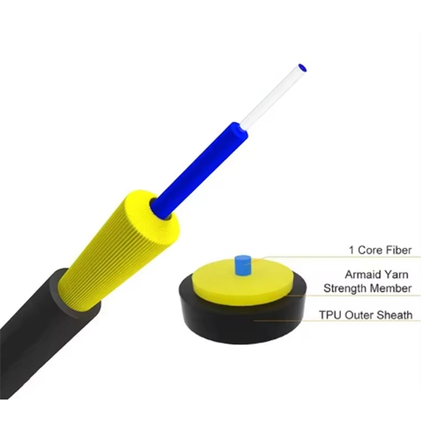
Bit Error Rate (BER) is a critical performance metric in optical communications that measures the number of errors occurring in a transmitted data stream over a certain period. It is defined as the ratio of the number of bits received in error to the total number of bits transmitted. This ratio is most often expressed using scientific notation (e., 10⁻⁸. USI has industry-leading capabilities in high-speed signal integrity and power integrity (SI/PI) design, as well as advanced thermal simulation and optical simulation using Zemax. In addition, we have strong expertise in high-speed PCB design utilizing mSAP and substrate PCB technologies. USI also. Unlock AI-driven, actionable R&D insights for your next breakthrough. As optical links are increasingly used for high-speed data. Even a digital data transmission system is not totally error-free — statistical fluctuations related to noise influences cause a small percentage of the transmitted bits to be corrupted. The average fraction of incorrectly transmitted bits is called the bit error rate. Offers precise, cost-efficient optoelectronic signal and anomaly testing for high-speed transceivers. · Use control board and replaceable.
[PDF]

This graph shows the market share of ai chatbots in Namibia based on over 3 billion monthly page views. Sorry, JavaScript is required to view Global Stats charts. Update Graph! View all regions. Market Forecast By Offering (Hardware, Software, Services), By Technology (Machine Learning, Natural Language Processing, Context-Aware Computing, Computer Vision), By Business Function (Finance, Security, Human Resources, Law, Marketing and Sales, Other Business Function (IT operations)), By. The Namibia Securities Exchange (“NSX”) is the only stock exchange in Namibia, with a total market capitalisation of US$ 145 billion as at end 2014, making it the second biggest exchange in Africa in those terms. The reason for this size is the large number of dual or secondary listings. The NSX. Huijue Group's energy storage solutions (30 kWh to 30 MWh) cover cost management, backup power, and microgrids. To cope with the problem of no or difficult grid access for base stations, and in line with the policy trend of energy saving and emission reduction, Huijue Group has launched an. How does 6Wresearch market report help businesses in making strategic decisions? 6Wresearch actively monitors the Namibia AI in Healthcare Market and publishes its comprehensive annual report, highlighting emerging trends, growth drivers, revenue analysis, and forecast outlook. This report offers comprehensive.
[PDF]
Standard length of 2. 44 Or 3 mtrs This length has been standardized as Handling, shipment, storage, site usage etc. Cable trays and auxiliaries shall be made of stainless steel complying with BS EN 10088-2 Grade 1. 4401 (ASTM Grade 316). Straight cable tray shall be supplied in standard lengths. Upto 300mm. Above 300mm width in 2. (WITH RUTERN FALANGE 2. Production at the factory is observed using modern practices of manufacturing methods in the steel. In practice, cable tray dimensions are a system of interrelated measurements —width, depth, length, and material thickness—that directly affect cable fill compliance, heat dissipation, structural loading, and long-term expandability. From an engineering standpoint, cable tray dimensions are not. association representing the major electrical equipment manufac-turers in the U. The Cable Tray ng standards, performance standards, test standards and application in this document have been tested extens ompetent professional en completely installed, without damage either to conductors or. Looking to buy a Stainless Steel Cable Tray in Kuwait? Jeetmull Jaichandlall (P) Ltd. is one of the trustworthy Stainless Steel Cable Tray Manufacturers in Kuwait that is here to fulfill all your wire mesh and netting tools needs. We believe in building fruitful business partnerships.
[PDF]

The formula for calculating electrical box size is: . The formula for calculating electrical box size is: . Free electrical load calculation tool for residential and commercial buildings. Calculate service entrance sizing, panel loads, demand factors, and ensure NEC Article 220 compliance. Important: Load calculations must comply with NEC Article 220 and local codes. Always verify calculations with a. How to choose a distribution box of the right size for a project based on load current? If you're like most electrical professionals, picking the right distribution box for your project can feel like navigating a maze. I've been in those shoes - staring at spec sheets, worrying about. The National Electrical Code (NEC) specifies minimum box sizes based on wire gauge and quantity. Proper sizing ensures safety, ease of maintenance, and compliance with regulations. This calculator helps you determine the minimum required box volume based on the number of wires, devices, ground wires, and clamps involved. This ensures compliance with electrical codes and prevents overcrowding. Choose a standard or custom box volume watch capacity update with clear pass or fail status plus tips examples CSV and PDF export for documentation Works for common sizes supports.
[PDF]
In 1880, and his assistant created a very early precursor to fiber-optic communications, the, at Bell's newly established in. Bell considered it his most important invention. The device allowed for the of sound on a beam of light. On June 3, 1880, Bell conducted the world's first wireless transmission between two buildings, some 213 meters apart. Due to its use of an atmospher.
[PDF]
Market Size by Fiber Type, by Deployment, by Cable Type, by End Use Industry – Global Forecast. The global fiber optic cable market was valued at USD 13 billion in 2024 and is estimated to grow at a CAGR of 10. The Fiber Optic Cable Market Report is Segmented by Cable Type (Armored Cable, Non-Armored Cable, and More), Fiber Mode (Single-Mode Fiber, Multi-Mode Fiber, and More), Installation Type (Aerial/Overhead, Underground/Buried, and More), End-User Industry (Telecommunication, Power Utilities and Smart. The global Fiber Optic Cable Market is anticipated to be worth USD 5. It is expected to grow steadily and reach USD 11. This growth represents a CAGR of 7. 21% during the forecast period from 2026 to 2035. I need the full data tables, segment breakdown, and. The fiber optics industry is projected to reach USD 6. 8 billion by 2029 from USD 3. Rapid expansion of data centers, cloud services, and 5G infrastructure is driving strong adoption of fiber optic solutions. 64% between 2023 and 2028. The market is experiencing significant growth, driven by the increasing demand for high-speed internet connectivity and the expansion of data centers.
[PDF]
The original unstructured record data for the defect of the relay protection devices (RPDs) may contain problems influencing the data mining, and it is lack of quantitative evaluation. So the purpose of this.
[PDF]

An optical module's actual transmit power measured by an optical power meter is lower than the nominal transmit power of the power module. The possible causes are: Bores of the optical module are contaminated. Stable optical power is the foundation of every high-capacity optical transport system. Even minor deviations—whether too high, too low, or unstable—can impact signal integrity, trigger service alarms, or interrupt traffic on DWDM, OTN, or long-haul optical line systems. This is the domain of Cell-to-Module (CTM) power loss, a series of. This paper reviews methods for reducing different optical and electrical loss mechanisms in PV modules and for increasing the optical gains in order to achieve higher CTM ratios. Various solutions for optimizing PV modules by means of simulations and experimental prototypes are recommended. Have you ever experienced an unexpected network outage due to the failure of an SFP/SFP+ optical transceiver? Network outages can bring your ability to communicate and work to a halt, and your IT team will likely be frantically looking for a solution. It is important to understand how to. This article provides an in-depth analysis of two key performance indicators of optical modules: transmitter power and receiver sensitivity. Transmitter power characterizes the average optical power output from the laser under rated conditions, while receiver sensitivity indicates the minimum.
[PDF]
There are several diagnostic methods to help troubleshoot fiber optic connectors, and the diagnostic method is to cross-section the fiber optic connector. This technology allows us to actually look inside the fiber optic connector to see defects and pinpoint the cause of. Fiber design and transmission technology have collaboratively evolved to increase bandwidth. Dig-ups dominate! Cablers have very little influence on the majority of causes of cable field failures. While a small percentage, we can examine the “intrinsic” cable failures and what is done to prevent. Connector failure is most frequently the result of a dirty or damaged end-face. Fiber-optic connector: SC type In the connector, the element that holds the fiber and provides the alignment positioning is the ferrule. The. In August of 1999, Boeing Corporation (Boeing) engineers being used on International Space Station flight a defect in the glass fiber (see Figure 1, “Rocket and NASA engineers and managers, Boeing created and reliability of the cable installed in the U. Fiber coupling can be accomplished by fusion splicing.
[PDF]
5 inch CETC Optic fiber OTDR AV6418,Fiber optic test tester,1310/1550nm,45/43dB large dynamic range,built in Optic power meter and VFL Description: AV6418 OTDR mainly used to measure the physical characteristics of optical fiber under test,such as the length,the transmission loss. 6. 5-inch display offers an event blind zone of 1 m and operates with locater This product is already in your quote request list. Measuring Measuring loss (dB) in the range between 800nm – 1700nm. Power AC/DC adapter; Input:100V~240V, 50/60Hz. Polarization extinction ratio (PER) is a measure of the degree to which light is confined in a principal linear polarization mode. It is defined as the ratio of the power in the principal polarization mode to the power in the orthogonal polarization mode after propagation through a device or. The ERM2xx Extinction Ratio Meters measure the polarization extinction ratio (PER) and the polarization angle of polarization-maintaining (PM) fibers. It features unmatched low cost, all wavelength options, a large dynamic range, and high resolution. The design adds a rotary polarizer to an optical power meter.
[PDF]

PC configuration software for Reyrolle products including Reydisp Manager 2, Reydisp Manager 1, and Reydisp Evolution. Doble RTS™ (RTS) is the premier protection testing software system for improving the work of testing relays and managing test records. Process consistency with power and flexibility set RTS software apart, and tremendous automation enables unmatched efficiency, accuracy and productivity. Apply your. Download documents, support information, software, video and audio content. IEC61850 Digital Substation Testing With 15 years experience in IEC61850 digital substation testing, KINGSINE portable relay testers are designed for comprehensive testing in both traditional and digital substations, including MU and IEC61850 compliant IEDs. Protection Relay Test Set/Kit KINGSINE. The commissioning of protection systems is an essential step to ensure the safety, reliability, and operational efficiency of electrical installations. In this context, the testing of protection relays and IEDs (Intelligent Electronic Devices) must be carried out with maximum precision, speed, and. A software designed to manage all aspects of protective relay testing using the Megger SMRT and FREJA models of relay testers. Facilitates steamlined and efficient relay protection testing through automation and relay modules. By using one of the over 400 relay templates with relay settings import. Portable at just 15 kg, the FREJA 300 is intended primarily for.
[PDF]

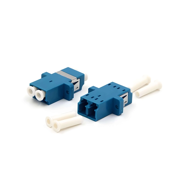
This fiber splicing dome enclosure comes with six splice trays that accommodate up to 96 unterminated cables to give you more flexibility in adjusting cable lengths and connection types directly on-site. The optical fiber splicing tray is designed to provide a location for storing and protecting optical cables and splicing. It is mainly used for management of cable junction box and wall mounted junction box. They are equipped with splice holders, compatible with all standard types of heat shrink or crimp type splice protectors, and provide enough space for storage and management of the excess fiber. PPC ofers a. Corning has a wide variety of hardware solutions to choose from to fit your cabling needs. Choose from racks, panels, modules, splice trays, ethernet fiber switches and other structured cabling components. Corning has a variety of hardware solutions including ethernet fiber switches, panels, racks. $ {cardName} unavailable for quantities greater than $ {maxQuantity}. Brief content visible, double tap to read full content. Would you like to tell us about a lower price? Found a lower price? Let us know. Although we can't match every price. Discover CommScope fiber splice trays, fiber optic splice trays, and a convenient fiber splice organizer. Each tray provides space for mounting fiber splice protectors and excess fiber. Optical fiber glass.
[PDF]
Modern Standard: For an average-sized home today, 200-amp service is the standard recommendation. It comfortably supports contemporary appliance loads, HVAC systems, and multiple electronic devices. Older/Smaller Homes: You might find 100-amp or 60-amp panels. To choose a home distribution box, you must count your circuits and add 30% spare space. Then, select a main switch that handles your total load. Finally, choose safety devices like RCBOs and Surge Protection Devices (SPD) for the best protection against faults and lightning. Let us look at the. The breaker box, or main electrical panel, is the central distribution point for a home's electrical service. It takes the main electrical service from the utility and divides it into individual circuits that run throughout the house. Whether you are installing outlets, switches, lighting fixtures, or junction connections, box size directly affects wire fill capacity, device fit, and installation quality. This article guides you through selecting a distribution box that is both affordable and safe, emphasizing key features, configuration, and practical considerations. Safety is the top priority when. Household distribution boxes are essential components in modern electrical systems, providing a centralized location for managing electrical circuits within a home. While many families are familiar with these boxes, there is often a lack of understanding regarding their specifications and proper.
[PDF]

