
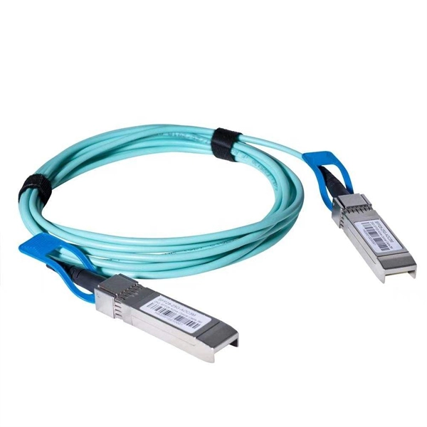
However, essentially, optical fiber patch cords are more like "finished connection lines", while optical fiber pigtails are "semi-finished connectors". The difference in this core positioning determines the vast disparity between them in structure, connection methods. Executive Summary: A fiber optic pigtail is one of the most commonly specified yet least understood components in structured cabling. Get the wrong connector type, the wrong polish, or skip proper fusion splicing technique—and you're looking at elevated signal loss, increased back reflection, and a. When you build or upgrade a fiber network, the same four words pop up everywhere— fiber optic (bare fiber), pigtail, patch cord, optical cable. They're related, but they are not interchangeable. Mixing them up drives costs higher, increases loss, and slows your rollout. The good news? Once you nail. A fiber pigtail is typically a fiber optic cable with one end factory pre-terminated fiber connector and the other exposed fiber. It is usually suitable for field termination using a mechanical or fusion splicer. The connector end plugs into devices like transceivers or patch panels, while the bare end is typically fusion spliced to a fiber optic cable. This setup ensures. As outlined in T13: Fiber Optic Fundamentals, an optical fiber is a coaxial cylindrical dielectric waveguide with a core refractive index exceeding that of its cladding.
[PDF]
ORL measures the amount of light reflected back toward the source in a fiber optic system— higher ORL (in dB) means less reflection and better performance. Poor ORL is commonly caused by dirty connectors, poor splices, mismatched connector types, or damaged fibers. Reflectance (which has also been called "back reflection" or optical return loss) of a connection is the amount of light that is reflected back up the fiber toward the source by light reflections off the interface of the polished end surface of the mated connectors and air. It is also called. The maximum optical reflectance is limited by where the signal saturates at the top of the trace. Likewise, ORL is limited when any part of the signal saturates or the entire trace is. The closer the number is to zero, the higher the reflectance (meaning a poor connection). There are many different reasons that can cause poor reflection in a fiber optic system. Measured in decibels (dB), higher ORL values indicate a cleaner, higher-quality fiber with minimal reflections, which is ideal for. Reflectance is a critical parameter in Optical Time-Domain Reflectometer (OTDR) testing that measures the proportion of light reflected back from specific events within a fiber optic cable. ORL is measured using ORL meters.
[PDF]

This guide provides a detailed comparison of fiber distribution cabinets and fiber termination boxes, including their structure, functions, applications, and cost differences. This table highlights the fundamental differences between the two solutions. What Is a. In FTTH, FTTB, and other fiber access networks, terms such as Fiber Optic Termination Box, Fiber Distribution Box (FDB), and ODF (Optical Distribution Frame) are frequently mentioned. Although they all belong to the optical distribution and management system, their. In fiber optic networks, choosing the right equipment for cable management and distribution is essential for ensuring performance, scalability, and long-term reliability. In practice, this confusion leads to incorrect network design, inefficient installation, and long-term maintenance challenges. Let's look at the position of various fiber box in. In modern FTTH and FTTx networks, several types of fiber management hardware ensure reliable optical connectivity from the central office to the end user. Fiber closure protects spliced fibers in backbone and feeder lines, fiber box (or fiber distribution box) organizes and splits fibers in.
[PDF]

An Optical Splitter, also known as a beam splitter, is a passive optical device that divides a single input optical signal into two or more output signals. Conversely, it can also combine multiple signals into one. Knowing the difference between a splitter and an optical coupler helps you build better networks. You make your network work better when you pick the right device for each job. You can connect many users to one port with 1:n or 2:n splitters. By dividing a single optical signal from a central Optical Line Terminal (OLT) into multiple outputs for Optical Network Terminals (ONTs) at users' homes, splitters eliminate the need for dedicated fibers to each residence—slashing infrastructure costs while scaling network reach. This guide. In a Passive Optical Network (PON), a single optical fiber carries massive amounts of data using light. Signal Input: The fiber splitter receives the optical signal from the upstream network node and enters the splitter through the input fiber. Signal Distribution: Inside the splitter, according to the design structure and different. Splitters are passive optical devices that divide or combine optical signals, and they come in various types, including power splitters, uneven splitters, and wavelength-division multiplexing (WDM) splitters. Each type serves specific applications, enabling efficient use of optical infrastructure.
[PDF]

Solar energy offers data centers a path to reduce their carbon footprint and operational expenses. Major tech companies like Google and Apple are already leading the way, demonstrating that solar-powered data centers are environmentally responsible and economically viable. Data centers are the backbone of our digital world, powering everything from streaming services and cloud storage to remote work platforms and IoT devices. As our reliance on digital infrastructure grows, so does the energy consumption of these mission-critical facilities. Currently, data centers. Solar offers clean power at predictable costs, can be built fast at many scales, and pairs well with batteries to deliver reliability. In this article, we explain why data centers use so much energy, how solar powers data centers, how batteries and microgrids keep servers online, and why these. 2022 to 35 gigawatts (GW) in 2030. The United States accounts f d tap into suitable energy sources. Renewable energy is the answer, but it must be cost-efective, able to meet enormous demand without inte zed by explosive growth and demand. The emergence of AI, data streaming, cloud computing, and.
[PDF]
Calculate cable tray fill ratio, weight loading, and derating factors for multi-standard compliance. This calculator features an interactive interface with advanced visualizations. Open the full calculator for the best experience. Our free calculator helps you determine the correct tray size based on NEC and IEC standards. Follow these simple steps: Define Tray Dimensions: Enter the width and depth of your planned cable tray (in mm or inches). Select Fill Standard: Choose 40% for power cables (NEC compliant) or 50% for. Stop Costly Cable Tray Installation Errors Now: Avoiding Mistakes in Instrumentation Cable Tray Installation: A Guide for EPC Projects Cable tray sizing in real EPC projects is not limited to simple area calculation. Save your cable tray sizing calculator results as branded PDF. The Cable Tray Sizing Calculator is an electrical calculator tool designed to determine the correct cable tray dimensions for electrical installations. How to find. Determine the total usable cross-sectional area of the cable tray by multiplying its width by its height (or depth). For mixed cables, sum the areas of all individual cables. Cable management is the unsung hero of modern infrastructure. Whether you are running heavy copper for a UPS Backup System or delicate fiber optics for a CCTV Security Network, the physical.
[PDF]

Cable Trays* — Max two 24 in. (610 mm) wide by max 6 in. (151 mm) deep open-ladder cable tray with channel-shaped side rails formed of 0. 54 mm) thick aluminum or min 0. In practice, cable tray dimensions are a system of interrelated measurements —width, depth, length, and material thickness—that directly affect cable fill compliance, heat dissipation, structural loading, and long-term expandability. From an engineering standpoint, cable tray dimensions are not. Perforated Cable Tray System expertly constructed from high-grade stainless steel, offering exceptional durability and resistance to corrosion. With side height 100mm. A properly designed and installed cable tray system will provide. Studs — Wall framing to consist of wood studs or channel shaped steel studs. Wood studs to consist of nom 2 by 4 in. Additional studs shall be used to completely frame. Best Size: Here, deep trays (75mm to 150mm) are used since power cables are typically thick and heavy. Data cables, such as your Wi-Fi or computer ones, are extremely sensitive. They do not get hot; however, they do not like to hang or sag. In case a data cable folds in an excessive manner, the. ect the minimum bend ra-dius for cables as they exit the bottom of the cable tray. A rung spacing of 6 to 9 inches (150 to 230 mm) is preferable when the cable tray cont d for instrumentation and control applications that require additional protec eferred to support and protect numerous small.
[PDF]