Watch as we take you through the entire manufacturing process step by st. How to Make Electrical Pigtails: This is a basic tutorial on what electrical pigtails are and how to make them. Disclaimer: Always use multiple sources and do your homework before performing any electrical work. Also, make sure all work is done within national and local code. Combining is putting the layers of linerboard and medium together to form complete corrugated board. Medium is engineered to form easily into flutes as it is fed between two large gear-like rollers on the Wet End of the corrugator. Linerboard is engineered to remain flat as it adheres to the top. A corrugated box is a packaging carton made of a fluted (wavy) inner layer sandwiched between two flat sheets of paper. The thickness of the inner and outer sheets can be customized as per a brand's needs and the nature of the product. The three-layer structure creates a box that is both strong and. Pigtails act as bridges, allowing you to connect several wires to a single point without overloading connections. Professionals often prefer this method because it isolates issues, protecting downstream circuits from cascading failures. Why does this matter? Modern systems demand precision. A. The corrugated box manufacturing process involves several stages, beginning with paper rolls and ending with finished packaging boxes ready for shipment. These paper rolls are loaded onto the.
[PDF]

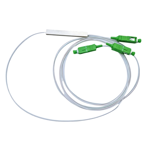
This standard covers the construction, mechanical, electrical, and optical performance, installation guidelines, acceptance criteria, test requirements, environmental considerations, and accessories for a nonmetallic, all-dielectric self-supporting (ADSS) fiber optic cable. An All-Dielectric Self-Supporting (ADSS) cable operates without metallic messengers, relying entirely on its aramid yarn strength members. For a typical 12-fiber ADSS cable with a 8. AFL-ADSS® (All-Dielectric Self-Supporting) cable is ideal for installation in distribution as well as transmission environments. This guide provides general recommendations for the selection of methods, equipment, and tools for the stringing of ADSS (All Dielectric Self-upporting) fiber optic cables including short and Long Span ADSS cables. The installation methods for ADSS cables are essentially the same as those used for. This Installation Manual is a recommendatory installation document provided by HANGZHOU ZION COMMUNICATION CO. The installation manual is established based on the newest issued international standards such as lEEE Std 1222: 2004, "lEEE standard for all-dielectric. Round aramid reinforced ADSS cable for intermediate and long spans, 4 – 96 fibres. VDE: A- DF 2Y (ZN) 2Y This specification covers a family of optical cables with 4 - 96 fibres for intermediate and long spans.
[PDF]
This video shows real on-site footage of electrical installation, demonstrating safe and standardized wiring methods used by professionals. What is the Price of Electrical Distribution Boxes? What are the common sizes for Distribution Boxes? How to Estimate the Size of the Box that I Want? Can I Customize a Distribution Box? How to Choose a Suitable Electrical Distribution Box? How does a Distribution Box Work? What's the Difference. In modern electrical systems, cable distribution boxes (also known as electrical distribution boxes or distribution boxes) play a crucial role as the key hub for managing, distributing, and protecting circuits. Whether it is residential buildings, commercial facilities or industrial sites, the. Ensure safe placement: install in dry, accessible areas with good ventilation and at appropriate height (typically ~1. Practice good wiring: secure grounding, neat cable management, proper insulation, and correct wire gauge and breaker size. Include protection devices like breakers, fuses, and. Plan of electrical installations for a shopping center; electrical installation; lightning; power outlets; single-line diagrams and load chart; typical details. It discusses key considerations for wiring types, circuit diagrams, load estimations, and costing. The main sections cover electrical service and supply, internal distribution, residential distribution.
[PDF]
IEC 61537 is the internationally recognized benchmark for metal cable tray systems. It applies to cable trays made of steel, stainless steel, aluminum, or other metallic materials. The standard ensures these systems can handle the physical and electrical loads they're exposed to. association representing the major electrical equipment manufac-turers in the U. The Cable Tray ng standards, performance standards, test standards and application in this document have been tested extens ompetent professional en completely installed, without damage either to conductors or. Cable trays play a vital role in supporting electrical cables and wires in commercial, industrial, and utility installations. For proper installation, design, and maintenance, adherence to international standards is essential. One of the most recognized frameworks globally is the IEC standard for. The B-Line series Cable Tray Manual was produced by our technical staff. The following pages address the 2014 National Electrical Code® requirements for cable tray systems as well as design. This publication is intended as a practical guide for the proper and safe* installation of cable ladder systems, cable tray systems, channel support systems and associated supports. These guidelines will be useful to engineers, contractors, and maintenance personnel. This is why proper planning and execution are.
[PDF]
In this guide, we'll walk you through the entire process of preparing fiber optic cable for splicing and termination to fiber connectors. We'll explore the necessary tools, safety precautions, and step-by-step procedures for cable connectors, mechanical and fusion. In this guide, you will find a chronological description of the fusion splicing process, the principal technical standards, and answers to the real-life questions network engineers and procurement teams may have. Therefore, we will also touch on cost factors, risk management, and best practices in. In this guide, we cover the basics of fiber optic splicing, how to perform splicing using two different methods, and finally some best practices to perform good fiber splicing. What is Fiber Optic Splicing and Why is it Needed? – #1. Two types of splices are used in fiber optic cabling one is Mechanical the other is Fusion. Before jumping into the physical steps, it's important to understand the two primary methods of fiber splicing: fusion splicing and. Learn how to splice fiber optic cable step by step in this complete guide! In this video, you'll see the full fiber splicing process — from fiber preparation, cleaving, and fusion splicing to final testing. For network managers and technicians, a poor splice can lead to significant signal degradation, network downtime, and costly troubleshooting.
[PDF]
Spectrophotometry is a tool that hinges on the quantitative analysis of molecules depending on how much light is absorbed by colored compounds. Important features of spectrophotometers are spectral bandwidth (the range of colors it can transmit through the test sample), the percentage of sample transmission, the logarithmic range of sample absorption, and sometimes a percentage of reflect. SummarySpectrophotometry is a branch of concerned with the quantitative measurement of the reflection or transmission properties of a material as a function of wavelength. Spectropho. Invented by in 1940 , the spectrophotometer was created with the aid of his colleagues at his company National Technical Laboratories founded in 1935 which would become Beckman Instrument Company a. There are two major classes of devices: single-beam and double-beam. A double-beam spectrophotometer compares the light intensity between two light paths, one path containing a reference sample and the other the te.
[PDF]
In this guide, we break down the two core stages of optical fiber manufacturing: preform production (shaping the precursor material) and fiber drawing (transforming the preform into thin, usable fiber). Explore the optical cable manufacturing process. Learn about raw materials, fiber drawing, cabling, and quality control in modern optical cable manufacturing. Is your digital life lagging? Slow streams, dropped calls? The unsung hero of our connected world, the optical cable, might be the key, and. Fiber optic cables are the backbone of today's high-speed internet, telecommunication systems, and data transfer technologies. Fiber optic technology has revolutionized the way information is transmitted, offering numerous advantages over traditional copper wiring. What makes fiber optic cables special is their ability to. The production of optical fiber is a precision-driven process that transforms raw materials like silicon tetrachloride into ultra-thin, high-performance fibers capable of transmitting terabits of data over thousands of kilometers. This manufacturing journey directly impacts the fiber's mechanical.
[PDF]
All interval wiring should conform to the relevant International Best Practices. For general site work additional precautions are necessary. Other than supplies for welding purposes, cables carrying a voltage to earth in excess of 65V should have co. All interval wiring should conform to the relevant International Best Practices. For general site work additional precautions are necessary. Other than supplies for welding purposes, cables carrying a voltage to earth in excess of 65V should have continuous metal armour or sheath which has been effectively earthed. Where trailing cables are concern. An RCD or ELCB is to be installed to all final distribution boards and tested before use on each shift. To allow only the use of 110 volt for portable electric tools. Earth Leads Earth leads must be colored yellow and green, and yellow should be of stranded copper or copper alloy with a cross section of at least 6 sq.mm. The maximum size need not e. All extension cables / cords should have a current inspection tag affixed and should be checked for damage prior to use. Extension cables / cords in one office should not be used to supply power to another office, building or adjacent offices. Cables / Cords may not run through doors, windows or ceilings unless for the purposes of temporary constru.
[PDF]
OPGW cable joint box installation involves several key stages: selecting the appropriate location, preparing both the cable and the joint box, splicing fibers, and sealing the joint box properly. Adhering to these steps ensures optimal performance and longevity of the. This manual is formulated in accordance with IEEE 1138 - 2008 and IEEE 524 - 1992, etc. OPGW has dual functions of aerial ground wire and fiber communication. This guide provides a comprehensive overview of OPGW joint box installation, highlighting its importance and offering step-by-step instructions to master the process. The company is the world's best opgw joint box installation supplier. We are your one-stop shop for all needs. Our staff are. This document covers all the activities usually performed by PRYSMIAN for on-site installation of OPGW fibre optic cables, including transport, installation, accessory assembly, verification of optical transmission characteristics and final certification. AFL provides detailed installation instructions on proper techniques for installing OPGW cable. Please review the document (WI-0298 Rev 1) before proceeding with installation. Furthermore, it explains how these elements ensure both structural stability and long-term performance. These accessories provide mechanical strength and secure connections.
[PDF]

This complete guide explores everything you need to know about ODFs — from their structure, types, and key components, to installation best practices and modern design trends. Clients facing the exact demands of specialized environments—whether it's ultra-low-latency AI clusters, space-constrained military installations, or high-density telecom exchange points need more than off-the-shelf cabling. At FS, we place the customer at the heart of our operations. We are. This white paper provides a comprehensive guide to designing future-proof fiber optic networks, emphasizing a core-to-edge architectural approach. Key focus areas include backbone topologies, optical loss budgeting, standards compliance, and strategies for optimizing high-density environments like. In modern data centers and enterprise networks, Optical Distribution Frames (ODF) serve as the backbone for organizing, terminating, and managing fiber optic connections. As data centers, enterprises, telecom operators, and smart-building infrastructures deploy increasingly dense fiber links, ODFs provide the structured. Fiber optic network design refers to the specialized processes leading to a successful installation and operation of a fiber optic network. It includes first determining the type of communication system (s) which will be carried over the network, the geographic layout (premises, campus, outside.
[PDF]