Watch as we take you through the entire manufacturing process step by st. How to Make Electrical Pigtails: This is a basic tutorial on what electrical pigtails are and how to make them. Disclaimer: Always use multiple sources and do your homework before performing any electrical work. Also, make sure all work is done within national and local code. Combining is putting the layers of linerboard and medium together to form complete corrugated board. Medium is engineered to form easily into flutes as it is fed between two large gear-like rollers on the Wet End of the corrugator. Linerboard is engineered to remain flat as it adheres to the top. A corrugated box is a packaging carton made of a fluted (wavy) inner layer sandwiched between two flat sheets of paper. The thickness of the inner and outer sheets can be customized as per a brand's needs and the nature of the product. The three-layer structure creates a box that is both strong and. Pigtails act as bridges, allowing you to connect several wires to a single point without overloading connections. Professionals often prefer this method because it isolates issues, protecting downstream circuits from cascading failures. Why does this matter? Modern systems demand precision. A. The corrugated box manufacturing process involves several stages, beginning with paper rolls and ending with finished packaging boxes ready for shipment. These paper rolls are loaded onto the.
[PDF]
In this guide, we break down the two core stages of optical fiber manufacturing: preform production (shaping the precursor material) and fiber drawing (transforming the preform into thin, usable fiber). Explore the optical cable manufacturing process. Learn about raw materials, fiber drawing, cabling, and quality control in modern optical cable manufacturing. Is your digital life lagging? Slow streams, dropped calls? The unsung hero of our connected world, the optical cable, might be the key, and. Fiber optic cables are the backbone of today's high-speed internet, telecommunication systems, and data transfer technologies. Fiber optic technology has revolutionized the way information is transmitted, offering numerous advantages over traditional copper wiring. What makes fiber optic cables special is their ability to. The production of optical fiber is a precision-driven process that transforms raw materials like silicon tetrachloride into ultra-thin, high-performance fibers capable of transmitting terabits of data over thousands of kilometers. This manufacturing journey directly impacts the fiber's mechanical.
[PDF]
GYXTW is a fiber optic cable that can serve overhead, buried and through-tube scenarios according to line design requirements. This loose sleeve is filled with a. GYXTW form of fiber optic cable is one that has an outer tube structure laid in the air, most suitable for outdoor environments of overhead application. It conforms to the concept of design of central tube cable, which is also known as loose tube cable. Known for its durability and flexibility, this cable plays a critical role in both indoor and outdoor applications. This article explores the features, benefits, applications, and. GYXTW is a compact outdoor fiber optic cable design widely used in access and distribution networks, especially where space efficiency and mechanical reliability are required. GYXTW adopts a central loose tube structure, with optical fibers placed inside a gel-filled tube for moisture protection. GYXTW fiber optic cable is constructed by. This cable is used across different project and manufacturing stages — from network deployment to in-house cable production. Reliable finished cable supply for overhead network deployment, utility communication projects, and infrastructure integration. Used to supplement production capacity, expand. This specification covers the design requirements and performance standard for the supply of optical fiber cable.
[PDF]
All interval wiring should conform to the relevant International Best Practices. For general site work additional precautions are necessary. Other than supplies for welding purposes, cables carrying a voltage to earth in excess of 65V should have co. All interval wiring should conform to the relevant International Best Practices. For general site work additional precautions are necessary. Other than supplies for welding purposes, cables carrying a voltage to earth in excess of 65V should have continuous metal armour or sheath which has been effectively earthed. Where trailing cables are concern. An RCD or ELCB is to be installed to all final distribution boards and tested before use on each shift. To allow only the use of 110 volt for portable electric tools. Earth Leads Earth leads must be colored yellow and green, and yellow should be of stranded copper or copper alloy with a cross section of at least 6 sq.mm. The maximum size need not e. All extension cables / cords should have a current inspection tag affixed and should be checked for damage prior to use. Extension cables / cords in one office should not be used to supply power to another office, building or adjacent offices. Cables / Cords may not run through doors, windows or ceilings unless for the purposes of temporary constru.
[PDF]

This standard covers the construction, mechanical, electrical, and optical performance, installation guidelines, acceptance criteria, test requirements, environmental considerations, and accessories for a nonmetallic, all-dielectric self-supporting (ADSS) fiber optic cable. An All-Dielectric Self-Supporting (ADSS) cable operates without metallic messengers, relying entirely on its aramid yarn strength members. For a typical 12-fiber ADSS cable with a 8. AFL-ADSS® (All-Dielectric Self-Supporting) cable is ideal for installation in distribution as well as transmission environments. This guide provides general recommendations for the selection of methods, equipment, and tools for the stringing of ADSS (All Dielectric Self-upporting) fiber optic cables including short and Long Span ADSS cables. The installation methods for ADSS cables are essentially the same as those used for. This Installation Manual is a recommendatory installation document provided by HANGZHOU ZION COMMUNICATION CO. The installation manual is established based on the newest issued international standards such as lEEE Std 1222: 2004, "lEEE standard for all-dielectric. Round aramid reinforced ADSS cable for intermediate and long spans, 4 – 96 fibres. VDE: A- DF 2Y (ZN) 2Y This specification covers a family of optical cables with 4 - 96 fibres for intermediate and long spans.
[PDF]
IEC 61537 is the internationally recognized benchmark for metal cable tray systems. It applies to cable trays made of steel, stainless steel, aluminum, or other metallic materials. The standard ensures these systems can handle the physical and electrical loads they're exposed to. association representing the major electrical equipment manufac-turers in the U. The Cable Tray ng standards, performance standards, test standards and application in this document have been tested extens ompetent professional en completely installed, without damage either to conductors or. Cable trays play a vital role in supporting electrical cables and wires in commercial, industrial, and utility installations. For proper installation, design, and maintenance, adherence to international standards is essential. One of the most recognized frameworks globally is the IEC standard for. The B-Line series Cable Tray Manual was produced by our technical staff. The following pages address the 2014 National Electrical Code® requirements for cable tray systems as well as design. This publication is intended as a practical guide for the proper and safe* installation of cable ladder systems, cable tray systems, channel support systems and associated supports. These guidelines will be useful to engineers, contractors, and maintenance personnel. This is why proper planning and execution are.
[PDF]
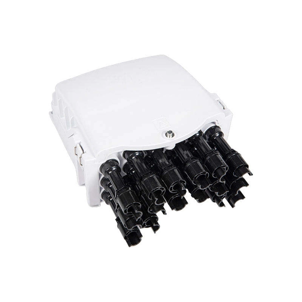
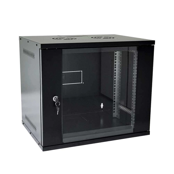
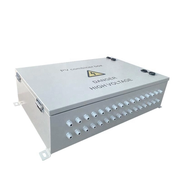
This video shows real on-site footage of electrical installation, demonstrating safe and standardized wiring methods used by professionals. What is the Price of Electrical Distribution Boxes? What are the common sizes for Distribution Boxes? How to Estimate the Size of the Box that I Want? Can I Customize a Distribution Box? How to Choose a Suitable Electrical Distribution Box? How does a Distribution Box Work? What's the Difference. In modern electrical systems, cable distribution boxes (also known as electrical distribution boxes or distribution boxes) play a crucial role as the key hub for managing, distributing, and protecting circuits. Whether it is residential buildings, commercial facilities or industrial sites, the. Ensure safe placement: install in dry, accessible areas with good ventilation and at appropriate height (typically ~1. Practice good wiring: secure grounding, neat cable management, proper insulation, and correct wire gauge and breaker size. Include protection devices like breakers, fuses, and. Plan of electrical installations for a shopping center; electrical installation; lightning; power outlets; single-line diagrams and load chart; typical details. It discusses key considerations for wiring types, circuit diagrams, load estimations, and costing. The main sections cover electrical service and supply, internal distribution, residential distribution.
[PDF]

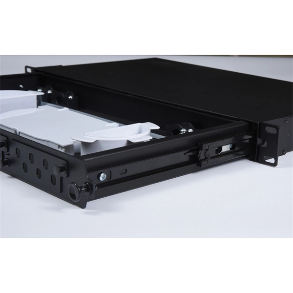
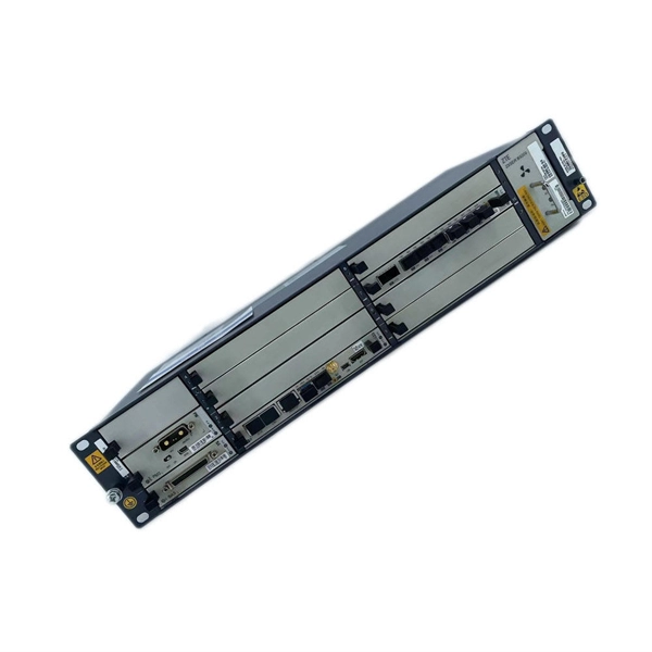
This complete guide explores everything you need to know about ODFs — from their structure, types, and key components, to installation best practices and modern design trends. Clients facing the exact demands of specialized environments—whether it's ultra-low-latency AI clusters, space-constrained military installations, or high-density telecom exchange points need more than off-the-shelf cabling. At FS, we place the customer at the heart of our operations. We are. This white paper provides a comprehensive guide to designing future-proof fiber optic networks, emphasizing a core-to-edge architectural approach. Key focus areas include backbone topologies, optical loss budgeting, standards compliance, and strategies for optimizing high-density environments like. In modern data centers and enterprise networks, Optical Distribution Frames (ODF) serve as the backbone for organizing, terminating, and managing fiber optic connections. As data centers, enterprises, telecom operators, and smart-building infrastructures deploy increasingly dense fiber links, ODFs provide the structured. Fiber optic network design refers to the specialized processes leading to a successful installation and operation of a fiber optic network. It includes first determining the type of communication system (s) which will be carried over the network, the geographic layout (premises, campus, outside.
[PDF]
OPGW cable joint box installation involves several key stages: selecting the appropriate location, preparing both the cable and the joint box, splicing fibers, and sealing the joint box properly. Adhering to these steps ensures optimal performance and longevity of the. This manual is formulated in accordance with IEEE 1138 - 2008 and IEEE 524 - 1992, etc. OPGW has dual functions of aerial ground wire and fiber communication. This guide provides a comprehensive overview of OPGW joint box installation, highlighting its importance and offering step-by-step instructions to master the process. The company is the world's best opgw joint box installation supplier. We are your one-stop shop for all needs. Our staff are. This document covers all the activities usually performed by PRYSMIAN for on-site installation of OPGW fibre optic cables, including transport, installation, accessory assembly, verification of optical transmission characteristics and final certification. AFL provides detailed installation instructions on proper techniques for installing OPGW cable. Please review the document (WI-0298 Rev 1) before proceeding with installation. Furthermore, it explains how these elements ensure both structural stability and long-term performance. These accessories provide mechanical strength and secure connections.
[PDF]

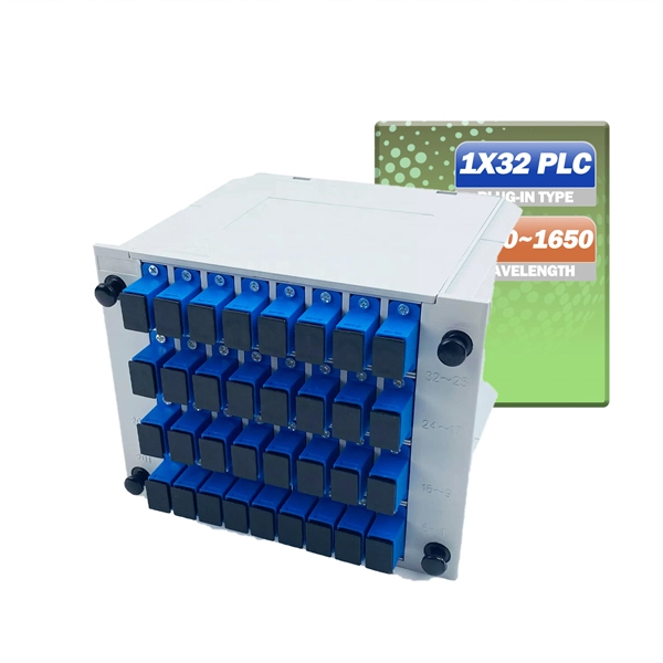
An Optical Splitter, also known as a beam splitter, is a passive optical device that divides a single input optical signal into two or more output signals. Conversely, it can also combine multiple signals into one. Knowing the difference between a splitter and an optical coupler helps you build better networks. You make your network work better when you pick the right device for each job. You can connect many users to one port with 1:n or 2:n splitters. By dividing a single optical signal from a central Optical Line Terminal (OLT) into multiple outputs for Optical Network Terminals (ONTs) at users' homes, splitters eliminate the need for dedicated fibers to each residence—slashing infrastructure costs while scaling network reach. This guide. In a Passive Optical Network (PON), a single optical fiber carries massive amounts of data using light. Signal Input: The fiber splitter receives the optical signal from the upstream network node and enters the splitter through the input fiber. Signal Distribution: Inside the splitter, according to the design structure and different. Splitters are passive optical devices that divide or combine optical signals, and they come in various types, including power splitters, uneven splitters, and wavelength-division multiplexing (WDM) splitters. Each type serves specific applications, enabling efficient use of optical infrastructure.
[PDF]
Single mode and multimode fiber optic cables are two different types of fiber optic cable aimed at different use cases. Single mode cables are typically made with a single strand of glass at their core, leading to a n.
[PDF]

Cable Trays* — Max two 24 in. (610 mm) wide by max 6 in. (151 mm) deep open-ladder cable tray with channel-shaped side rails formed of 0. 54 mm) thick aluminum or min 0. In practice, cable tray dimensions are a system of interrelated measurements —width, depth, length, and material thickness—that directly affect cable fill compliance, heat dissipation, structural loading, and long-term expandability. From an engineering standpoint, cable tray dimensions are not. Perforated Cable Tray System expertly constructed from high-grade stainless steel, offering exceptional durability and resistance to corrosion. With side height 100mm. A properly designed and installed cable tray system will provide. Studs — Wall framing to consist of wood studs or channel shaped steel studs. Wood studs to consist of nom 2 by 4 in. Additional studs shall be used to completely frame. Best Size: Here, deep trays (75mm to 150mm) are used since power cables are typically thick and heavy. Data cables, such as your Wi-Fi or computer ones, are extremely sensitive. They do not get hot; however, they do not like to hang or sag. In case a data cable folds in an excessive manner, the. ect the minimum bend ra-dius for cables as they exit the bottom of the cable tray. A rung spacing of 6 to 9 inches (150 to 230 mm) is preferable when the cable tray cont d for instrumentation and control applications that require additional protec eferred to support and protect numerous small.
[PDF]
What is a Vibration Optical Fiber Alarm System? A Vibration Optical Fiber Alarm System uses optical fiber sensors to detect vibrations and movements along a perimeter or infrastructure. These sensors are integrated into a fiber optic cable, which is then deployed along the area to be. Non-intrusive, EMI-resistant vibration sensing for critical infrastructure and harsh environments Optical fiber vibration sensors are transforming how industries monitor structural and mechanical systems in environments where traditional electronic sensors fall short. Using light modulation within. Advanced vibration sensing fiber optic detection system The one cable optical cable vibration detection and alarm system is a cable type structural intrusion detection and alarm system. The system uses optical cables as sensing units, uses computers to collect and control data, and realizes. Fiber optic intrusion detection uses specialized cables to sense and report any unauthorized access or disturbance along a protected area. You can think of these cables as a sensitive tripwire or a microphone that listens for unusual vibrations. It. At Hikvision, we offer optical fiber products that use light waves and optical fibers to detect and respond to environmental changes precisely. Our solution is perfect for perimeter intrusion detection, especially over long distances. Once triggering vibration alarm, it can be linked to video.
[PDF]
This complete guide explores everything you need to know about ODFs — from their structure, types, and key components, to installation best practices and modern design trends. Whether you're building a central office, data center, or FTTx distribution network, understanding the right ODF. Optical Distribution Frames (ODF) are indispensable components in optical communications networks. They provide efficient fiber optic management, connectivity, and protection. What is Optical Distribution Frame An Optical Distribution Frame (ODF) is the central hub of your fiber optic network. As data centers, enterprises, telecom operators, and smart-building infrastructures deploy increasingly dense fiber links, ODFs provide the structured. Enter the Optical Distribution Frame (ODF)—a foundational component that serves as the “nerve center” for fiber optic management, enabling seamless connectivity, efficient maintenance, and scalable growth. When fiber cables run wild, signals drop, repairs slow down, and headaches stack up. It keeps things neat, labeled, and under control. Whether in big data hubs or small networks.
[PDF]
LC connectors play an integral yet often overlooked role in enabling high-speed fiber optic communications. This guide dives into the engineering behind these compact connectors, their functionality, performance metrics, and applications across modern networks. LC connectors are a ubiquitous fiber. LC connectors provide reliable and high performance connectivity in fiber optic networks. The guide covers in depth their features, types, installation techniques, troubleshooting and applications. Learn how to use LC connectors for efficient networks. As a small-form-factor (SFF) interface, LC has become the default duplex connector in enterprise LANs, telco closets, and data-center topologies because it balances density, repeatability, and cost. This guide walks. It covers LC connectors, LC patch cables, uniboot designs, armored and ultra-low-loss variants, LC adapters and patch panels, LC attenuators, MTP/MPO-to-LC cassettes, LC-interfaced transceivers, and LC media converters. It also includes practical selection guidance, real-world deployment scenarios. Fiber optic connector is a device used to connect optical fibers, capable of transmitting and receiving optical signals. There have been many types of connectors developed for fiber cable. Single mode networks have used FC or SC.
[PDF]
