This comprehensive guide will explore the importance and benefits of this integration, provide an understanding of fiber optic cable and Ethernet ports, discuss their compatibility, and offer a step-by-step process for connecting them. Proper connection of fiber optic cables is essential to harness these benefits fully, as even minor errors can lead to significant performance issues like signal loss. This article will guide you through the necessary tools, materials, and methods on how to connect fiber optic cables effectively. Using an optical cable involves connecting it to the right equipment, ensuring proper installation, and testing the system for optimal performance. Here's a step-by-step guide on how to use optical cable effectively: 1. Check Compatibility of Equipment Ensure that your equipment (e., network. One powerful solution to achieve these goals is by connecting fiber optic cables with Ethernet ports. This comprehensive guide combines industry standards with field-tested practices to ensure you achieve a rock-solid. These transceiver modules are hot-swappable input/output (I/O) devices that plug into 100BASE, 1000BASE and 10GBASE ports (for SFP+), which connect the module port with the fiber-optic or copper network. The SFP transceiver modules are hot-pluggable I/O devices that plug into module sockets. The number one cause of signal loss in optical fiber installations is dirt on.
[PDF]
will introduce major upgrades to its Multi-Rail technology platform at ECOC 2025, targeting hyperscale optical transport with new efficiency, scale, and performance enhancements. Coherent Corp. SAXONBURG, PA, September 26, 2025 (GLOBE NEWSWIRE) – Coherent Corp. At the heart of the. SAXONBURG, Pa. At the heart of the. Simultaneously, coherent technology has emerged as the prevailing solution for Data Center Interconnection (DCI) applications, covering distances of 80~120km in the field of data communication. These evolving applications introduce new demands for coherent optical transceiver systems, steering the. Coherent optical module refers to a typically hot-pluggable coherent optical transceiver that uses coherent modulation (BPSK / QPSK / QAM) rather than amplitude modulation (RZ/ NRZ / PAM4) and is typically used in high-bandwidth data communications applications. Optical modules typically have an.
[PDF]
A passive optical network (PON) is a point-to-multipoint fiber network architecture that uses optical splitters to deliver high-bandwidth services from a single fiber to multiple end users without requiring active electronics in the field. While there are many subtle differences, a clear distinction between active optical networking and PON topology is PON's use of a. A passive optical network (PON) is a fiber-optic telecommunications network that uses only unpowered devices to carry signals, as opposed to electronic equipment. In practice, PONs are typically used for the last mile between Internet service providers (ISP) and their customers. In this use, a PON. A passive optical network sends data as light through fiber cables. You get internet, TV, and phone services with fewer cables and no powered splitters between you and your provider. What equipment do you need for PON at home? You need an optical network unit (ONU) at your home. By eliminating powered components between the service. Technology drives the broader adoption of passive optical LAN (also known as a passive optical local area network) across various sectors. Not having a long history as a passive optical network (PON), it is a better replacement for copper-based LANs in local area networks. This article covers every.
[PDF]
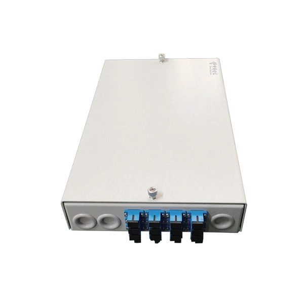
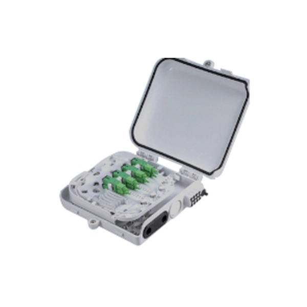
Manufacturers design fiber optic cabinets to protect fiber optic cables in indoor and outdoor environments. Also known as fiber optic enclosures or fiber entrance cabinets, these enclosures act as hubs where ca.
[PDF]

View price, stock and buy direct from Transceiver USA. Customize your 1/10/25/100/200/400G transceiver from data rate, connector type, compatilibity to form factor. With well-equipped lab, all FS custom optical transceivers are produced with high-quality components, offer a five-year warranty and fast shipping. Purchase from nearby warehouses. This article compares typical cost ranges across speeds and transceiver types, explains why prices vary, and gives practical guidance for choosing the right optics for a given. This post offers quick access to the SFP module price list by researching top vendors. SFP modules have been in large demand in data centers with the continuous development of optical communication. Also, the SFP module type upgrades rapidly. It has been experienced from the initial version of 1G. Optical Transceiver Modules/SFP, also called fiber optic transceiver or optical transceiver, is a typically hot-pluggable device used in high-bandwidth data communications applications. While optical transceiver development has gotten simpler over the years, it does involve full engineering development to design, validate, and qualify. Generally, the two main milestones in this phase are. An Optical Transceiver is a critical optoelectronic component that facilitates seamless electro-optical (E-O) and photo-electric (O-E) conversion within fiber-optic networks.
[PDF]
This report studies the global Optical Communication Module production, demand, key manufacturers, and key regions. The global Optical Module For Communication market size was US$ million in 2024 and is forecast to a readjusted size of US$ million by 2031 with a CAGR of %during the forecast period 2025-2031. 7% during the forecast period MARKET INSIGHTS The global Active Optical Module Market was valued at 5916 million in 2024 and is projected to reach US$ 15140 million. Major optical modules manufacturers and suppliers: Innolight, Eoptolink, Huagong Tech, Linktel, Accelink, CIG ShangHai CO. Upstream optical devices manufacturers and suppliers: TFC, T&S Communications, Advanced Fiber Resources, Borui Technology, Optowide Technologies. Upstream optical chips. Global Optical Modules Market Size By Product Type (Transceivers, Transponders), By Technology Type (Single-Mode Fiber (SMF), Multi-Mode Fiber (MMF)), By Application (Telecommunications, Data Centers), By Data Rate (10 Gbps, 25 Gbps), By Form Factor (SFP (Small Form-Factor Pluggable), SFP+. Additionally, strategic partnerships and acquisitions are prevalent, enabling companies to access new technologies, markets, and expertise. Market Share Analysis: Product Portfolio: Offering a comprehensive range of solutions across different segments, from access networks to long-haul.
[PDF]
This manual describes Inspect, a command-line tool for debugging TNS C/C++, COBOL, FORTRAN, Pascal, Screen COBOL, and TAL programs and snapshots on HP NonStopTM TNS/R and TNS/E systems. MFT (Mellanox/NVIDIA Firmware Tools) is a set of firmware management utilities for querying firmware details, performing firmware upgrades, and other configuration tasks. It includes four main components: mst, mlxburn, flint, and Debug Utilities. For full specifications, refer to the official. All commands were tested on HP/Aruba 5400 switches (specifically 5406Rzl2), but will work on any model with recent firmware versions (16. x or newer), except for the hardware features unavailable on smaller models, like VSF. This publication supports J06. 03 and all subsequent J-series RVUs, H06. Show general info: current CPU load, uptime, memory used/free, software. The HP 1-Port 1GbE Flex IO NIC is designed to work in the Flex IO port of select HP systems. Refer to platform specifications for compatibility. It utilizes a Realtek RTL8153 10/100/1000 Ethernet controller to provide an additional 1GbE LAN Port. 3az-2010, also known as Energy. HPE Insight Diagnostics is a hardware diagnostic tool. To start iLO with keyboard and monitor connected to the box - press F8 while booting Invoke virtual serial port. Starting text console. Press 'ESC (' to return to the CLI Session.
[PDF]

In this tutorial video, we will show you step-by-step how to safely and effectively remove an optocoupler from a circuit board using desoldering wick. We will walk you through the tools you will need, the proper technique for using the desoldering wick, and the precautions to take to av. more In. Whether you're replacing a faulty component, salvaging parts from an old board, or correcting a soldering mistake, knowing how to desolder effectively is essential. This guide will walk you through the tools, techniques, and best practices for desoldering components from a circuit board safely and. Desoldering is a process that removes the solder and components from a printed circuit board or any other type of electronic assembly. This is a meticulous process and it can easily damage the board, or the components, if not properly done. Thus, it is important to know how to desolder properly. If you're desoldering a battery from a circuit board, use flush cutters to cut each wire one-at-a-time to isolate the battery before you desolder the wires. Whenever possible, create an indirect path by soldering connectors onto the battery and the circuit board. This reduces the chance of an. Sorry, an unexpected error has occurred. Why Publish? The Ultimate Guide to Desoldering: From using desoldering irons to sketchily knocking breadboard components off on the side of a table, there are tons of ways to remove components from a circuit board.
[PDF]
BOSTON (January 7, 2025) – Total shipments of leading-edge datacom optical modules are projected to tally over $9 billion for 2024, according to the latest Optical Components Report from research firm Cignal AI. 6T optics will enter volume production in. According to the latest June 2025 Quarterly Market Update by renowned research firm LightCounting, the global optical transceiver market is set to rebound in Q2 2025 with a projected 10% quarter-over-quarter growth. The key growth driver is the rising demand for 800G Ethernet optical modules. This article unpacks the technologies powering this leap (silicon photonics, advanced modulation, and co-packaged optics), compares deployment paradigms, and delivers a tactical upgrade roadmap that balances performance, cost, and scalability. 5 million optical transceivers were deployed in 2024, a figure expected to rise to 34. Unit shipments of 400G and 800G modules have grown nearly fourfold over the past 12.
[PDF]

It emits a stable red light driven by a constant current source, which is coupled into the optical fiber through an interface to perform fiber fault detection functions. These include checking fiber connectivity and locating faults such as fiber breaks and bends. The B5 Rechargeable Red Light Pen is a professional 650nm visual fault locator designed for fiber optic network maintenance, installation, and troubleshooting. Its advanced rotary automatic lift laser head ensures smooth operation, while the integrated LED lighting improves visibility in low-light. Luxbond LBTEK Fiber Optic Red Light Pen (also known as a pen-style visual fault locator or fiber optic fault detector) uses a 650 nm semiconductor laser as the light source. Note: Meant for use with polished, terminated fiber cables. Always insert and remove the fiber connector without bending the connector to avoid breaking. The RPEN-210 is a necessity tool that should not be missing from any fiber plant manager or fiber optic installing technician. The Visual Fault Locator (VFL) Pen has a visible red light source centered on 650nm. Tool sends visible light over a fiber strand with a 10mW power, good enough to reach. ● Practical Design: Small size and lightweight, pen-type design with pouch make it portable. Design with a stainless steel head and aluminum body to prevent crash and dust, the case ground design prevents ESD damage efficiently Temp. Only registered users can write questions.
[PDF]

This comprehensive guide breaks down the internal structure, core components (TOSA, ROSA, lasers), and operational mechanisms of SFP optical modules, enriched with technical insights and real-world applications. SFP (Small Form-factor Pluggable) optical modules are compact, hot-pluggable transceivers that enable network equipment to connect seamlessly to fiber and copper links. As a leading provider of optical communication solutions, Weunion integrates these. One vital element in the data communication sector is the Small Form-factor Pluggable (SFP) module. In this blog, we will explore the inner workings of these modules, with a particular focus on three essential optical components: TOSA, ROSA, and BOSA. SFP modules are small, hot-swappable devices. Optical modules are devices used to connect network devices, transmit and receive data between network devices, and can be used to convert optical and electrical signals. The optical module is a very important component in an optical communication system. Think of it as the “translator” for your network equipment, converting electrical signals into optical signals. available with a variety of types of copper SFP and fiber SFPs, SFP+. This transceiver module is compliant wi h the small form-factor pluggable (SFP) multi-source agreement (MSA). They industrial performance with an extended operating temperature range. Through real-time monitoring, the DDM.
[PDF]

An Optical Time Domain Reflectometer (OTDR) is a precision tool used to detect faults and measure loss along fiber optic links by analyzing backscattered light from high-speed pulses. Download the PDF of the datasheet for an overview of the product features, important specifications, and ordering information. We are the measurement insight company committed to performance, and compelled by possibilities. Tektronix designs and manufactures test and measurement solutions to break. OTDR testing analyzes fiber optic cable performance from end to end by testing components along the cable, including connection points, bends, and splices. What Is an OTDR? What Is an OTDR? An OTDR is a powerful tool that helps technicians and engineers assess the health of fiber optic cables. Essential for both installation and maintenance, OTDRs ensure network reliability with accurate fault location. An OTDR (Optical Time Domain Reflectometer) is a measuring instrument intended to measure the transmission loss and distance of optical fibers, locate cable cuts, and evaluate the connection loss and reflectance (return loss) of fusion splices, mechanical splices, connector connections, etc. Also. Time Domain Reflectometry (TDR) is a well-established technique for verifying the impedance and quality of signal paths in components, interconnects, and transmission lines. The OTDR enables field technicians to rapidly, reliably, and.
[PDF]
Lighting Control System | Smart Lighting Wiring Setup | Full Guide In this video, you will learn how to connect and install a Lighting Control System step-by-step. This guide covers wiring setup, switch modules, dimming control, sensor setup and panel . as a guide for proper and reliable installation. The mounting location should e selected and prepared based on the application. All electrical wiring and mounting hardware (i. ) should be prepared with consideration of the requirements o cuit breaker before. Intelligent Lighting Controls' installation guides provide detailed instructions on how to install all of our solutions. The Lightolier Controls Optio Lighting Control Panels are high-performance, wall mounted lighting control panels which offer a wide range of dimming and relay modules to accommodate any lighting control application.
[PDF]

One of the core advantages of MPO patch cords is their high-density integration. Traditional patch cords have only 1-2 cores per cord, while MPO patch cords can integrate 12-48 cores, enabling multi-port connections with a single cord. Fiber cores are the heart of fiber optic cables, transmitting light signals that carry data. Made from either high-quality glass or plastic, the core plays a critical role in determining the cable's performance. The total number of cores for a 1pc fiber patch cable is calculated as the number of. Multi-core patch cords are fiber assemblies containing multiple fibers within a single cable jacket, typically available in 4, 6, 12, and 24-fiber configurations. The outer sheath is clearly marked with core count indicators. MTP/MPO cables are a class of high-density multi-core fiber optic connectivity solutions widely used in data centers and telecom networks, which are designed to achieve fast connection of multi-core fiber optics through a single interface. In the context of accelerating digitalization, the rational. The 16-core MPO patch cord, a high-density optical fiber connector, has become an ideal choice for 400G networks and beyond due to its superior optical performance, flexible compatibility, and efficient cabling capabilities. This report analyzes the key technical parameters, primary application.
[PDF]

An optical module's actual transmit power measured by an optical power meter is lower than the nominal transmit power of the power module. The possible causes are: Bores of the optical module are contaminated. Stable optical power is the foundation of every high-capacity optical transport system. Even minor deviations—whether too high, too low, or unstable—can impact signal integrity, trigger service alarms, or interrupt traffic on DWDM, OTN, or long-haul optical line systems. This is the domain of Cell-to-Module (CTM) power loss, a series of. This paper reviews methods for reducing different optical and electrical loss mechanisms in PV modules and for increasing the optical gains in order to achieve higher CTM ratios. Various solutions for optimizing PV modules by means of simulations and experimental prototypes are recommended. Have you ever experienced an unexpected network outage due to the failure of an SFP/SFP+ optical transceiver? Network outages can bring your ability to communicate and work to a halt, and your IT team will likely be frantically looking for a solution. It is important to understand how to. This article provides an in-depth analysis of two key performance indicators of optical modules: transmitter power and receiver sensitivity. Transmitter power characterizes the average optical power output from the laser under rated conditions, while receiver sensitivity indicates the minimum.
[PDF]