Rayleigh scattering -based distributed acoustic sensing (DAS) systems use fiber optic cables to provide distributed strain sensing. In DAS, the optical fiber cable becomes the sensing element and measurements are made, and in part processed, using an attached optoelectronic device. These systems enable precise measurement of temperature, strain, and acoustic signals along the entire length of an optical fiber. DFOS technology plays a crucial. ONYXTM the flagship platform from Sintela now delivers a customizable all-in-one, simple and cost-effective solution for your distributed fiber-optic sensing needs. Representing the next step in the evolution of Distributed Fiber Sensing, ONYX™ converts existing telecommunications fiber-optic cable. Distributed acoustic sensing systems (DAS) are fiber optic based optoelectronic instruments which measure acoustic interactions along the length of a fiber optic sensing cable. The unique feature of a distributed acoustic sensing system is that it provides a continuous (or distributed) temperature. Distributed Acoustic Sensing (DAS) is a cutting-edge technology that uses optical fiber to sense and identify multiple parameters over extended distances remotely. The technology leverages the Rayleigh backscatter theory to detect vibrations and sounds along the fiber Fiber optic-based Distributed.
[PDF]

Distributed Fiber Optics Sensing (DFOS) is a mature technology, with known, tested, verified, and even certified performance of various interrogators and measurement methods, which include Distributed Temperature Sensing (DTS), Distributed Temperature-Strain Sensing. Distributed Fiber Optics Sensing (DFOS) is a mature technology, with known, tested, verified, and even certified performance of various interrogators and measurement methods, which include Distributed Temperature Sensing (DTS), Distributed Temperature-Strain Sensing. Distributed Fiber Optics Sensing (DFOS) is a mature technology, with known, tested, verified, and even certified performance of various interrogators and measurement methods, which include Distributed Temperature Sensing (DTS), Distributed Temperature-Strain Sensing (DTSS), and Distributed Acoustic. FEBUS Optics is the world reference in DFOS, distributed fiber optic sensing systems (DAS, DTS and DSS), to reduce the environmental impact of human activity, protect people, and optimize production. FEBUS provides state-of-the-art devices and turnkey solutions based on its patented technologies.
[PDF]

Optical return loss is the amount of light that is reflected back to the source, this reflected light is measured at each connector and splice at each point over the entire fiber link. This is always measured in dB (decibels) and will be displayed as a negative number. The closer the number is to. The polish of a singlemode fiber endface plays a significant role in reflectance. Understand what you need before you specify. The Institute of Electrical and Building the ORL story Electronics Engineers (IEEE) recently Within a fiber-optic channel or path-released new specifications within way. Optical Return Loss (ORL) in fiber optics refers to the amount of light that is reflected back toward the source in a fiber link. ORL is usually expressed in decibels (dB) as a positive value, with. Return loss (RL) is also called reflection loss. When high-speed signals enter or exit a part of an optical fiber, such as an optical fiber connector, discontinuity and impedance mismatch may cause reflection, which is the return loss of an optical fiber. Poor ORL is commonly caused by dirty connectors, poor splices, mismatched connector types, or damaged fibers. ORL is measured using ORL meters. Home Coherent Optics Optical Return Loss (ORL) Explained Comprehensive Guide to Understanding and Managing Back-Reflections in Fiber Optic Systems What is Optical Return Loss (ORL)? Optical Return Loss (ORL) is a critical parameter in fiber optic systems that quantifies the amount of light.
[PDF]
This paper presents a method that integrates neural networks with arrayed waveguide gratings (AWGs) for the demodulation of fiber-optic sensors based on the Vernier effect and a novel, to our knowledge, Fabry–Pérot (FP) strain sensor structure. This paper addresses the issue of low demod-ulation accuracy in interferometric signals caused by sig-nificant errors in direct peak finding and positioning dur-ing multi-peak demodulation of fiber-optic MEMS Fabry Perot Sensors. To tackle this problem, we propose a novel approach that involves. Accurate demodulation of fiber-optic sensors is crucial for real-world engineering applications in monitoring and control. There are many demodulation methods that can be applied to fiber optic Fabry–Pérot.
[PDF]
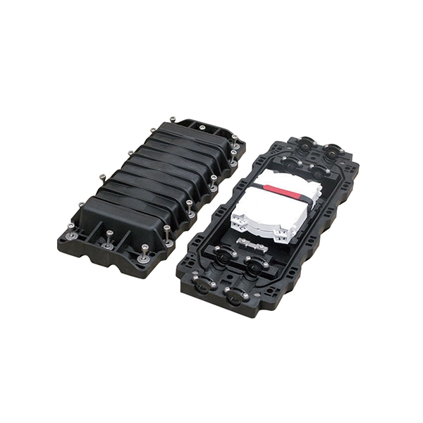
Different methods have been developed to measure cable forces, including the traditional direct strain measurement method, the oil pressure meter method, the low-cost vibration frequency method, the high-accuracy magnetic flux sensor method in the lab., and acoustic. This study aimed to develop a spiral deployment scheme of distributed fiber optic sensors (DFOS) and to monitor/assess the post-tensioned force in seven-wire twisted steel cables, based on the pulse-pre-pump Brillouin optical time domain analysis. Each DFOS was placed in a spiral shape between two. Distributed Optical Fiber Sensing (DFOS) transforms standard fiber optic cables into powerful sensors capable of detecting temperature, strain, and acoustic signals at thousands of measurement points over long distances. Such capabilities. l method of measuring force by means of bending a Fiber Fabry-Perot-{FFP-) resonator is described. This interferometric FFP-sensor is easily applicable to AC orce measurements, but makes temperature compensati on schemes necessary if DC ntity that can various measuring parame, accelerat of di. Distributed sensors hold a unique position in the realm of sensing technologies. Unlike point sensors, they can measure and provide a continuous spatial distribution of a physical quantity, effectively creating a mapped profile of the parameter of interest. A well-known example is RADAR, and more.
[PDF]
Recent advances in devices and applications of high-birefringence fiber loop mirror sensors are addressed. In optical sensing, these devices may be used as strain and temperature sensors, in a separate or in a simultaneous measurement. It is able to work over a long low refractive index analyte range from 1. This modified simple structured hexagonal PCF has high birefringence in the. Birefringent filters (or Lyot filters, as their implementation is most widely used in lasers) are popular radiation wavelength selectors. Their adaptations to fiber lasers are quite diverse and feature many original solutions.
[PDF]
This is the power of fiber optic sensing, a technology that transforms ordinary optical fibers into the digital world's sensory network. In 2023, researchers turned submarine cables into earthquake warning systems and gave electric vehicles “optical nerves” to prevent battery failures. This article digs into a pretty big leap in optical fiber sensing technology: a method that brings in Long Short-Term Memory (LSTM) neural networks to finally get around those stubborn free spectral range (FSR) limits in interferometric sensors. By blending photonics with modern machine learning. These systems are utilized for monitoring various physical parameters like temperature, strain, and pressure with high precision and reliability. Within the FOS market, several different technologies are available, each offering unique advantages and addressing specific application needs. At the heart of this innovation lies the integration of Long. The Fiber Optic Sensing Association (FOSA) is dedicated to accelerating the use of distributed and quasi-distributed optical fiber sensing technologies.
[PDF]
Distributed fibre optic sensing, including DTS and DTSS technologies, has a wide range of applications across various industries. Here are some key areas where these innovative technologies are making.
[PDF]

Researchers have unveiled a groundbreaking fiber-optic sensing technique capable of detecting strain and displacement with remarkable precision. This innovative method involves analyzing interference patterns within the electrical spectrum of a photodetected signal. The same principle can also be extended to displacement sensing using an air-gap structure between. What this article is about: Researchers at Yokohama National University have shown a new fiber-optic sensing method that reads interference patterns straight from the electrical spectrum produced by a photodetector. They used a polymer optical fiber-based single-mode–multimode–single-mode (SMS). Electrical-domain interference in polymer optical fibers offers a simpler route to fast sensing without conventional optical-spectrum analysis. This image summarizes the newly demonstrated sensing principle. Published in IEEE Sensors Journal on April 27, 2026. Measured in real-time, Sensuron's Fiber Optic Sensing technology ensures precise measurement and optimal performance. Our range of. Distributed Optical Fiber Sensing (DFOS) transforms standard fiber optic cables into powerful sensors capable of detecting temperature, strain, and acoustic signals at thousands of measurement points over long distances. This technology is revolutionizing industries from infrastructure monitoring.
[PDF]
Distributed Fiber Optic Sensing (DFOS) systems, using coherent light pulses, detect physical characteristics such as temperature and strain. DFOS enable localized measurements over long distances, leveraging Rayleigh, Brillouin, and Raman scattering. This review summarizes recent progress and emerging trends in multiparameter optical fiber sensing, emphasizing techniques that enable the simultaneous measurement of temperature, strain, acoustic waves, pressure, and other environmental quantities within a single sensing network. This technology is revolutionizing industries from infrastructure monitoring. Distributed Fiber Optic Sensing (DFOS) systems provide critical asset monitoring by utilizing standard fiber optic cables as sensors. These systems enable precise measurement of temperature, strain, and acoustic signals along the entire length of an optical fiber. Such capabilities.
[PDF]
They can weigh between 60 to 200 kg per kilometer (39. 7 to 132 pounds per 1000 feet), depending on the design and materials used. The weight of fiber optic cables can vary widely based on the factors mentioned above. However, some general guidelines can provide a rough estimate: Indoor Fiber Optic Cables: These are typically lighter as they require less protection. Indoor cables can weigh anywhere from 10 to 30 kg per. Fiber per Tube *: No of tube(13-24) shall be with black tracer but black* tube(20) with white tracer. Fiber per Tube *: Tube identification with one black stripe. In case of Black tube with white marking. This cable is perfect for headend termination to a fiber backbone, termination of fiber rack systems, multi-floor deployment where select fibers are used at each floor, or intra-building backbones. It is suitable for all indoor applications where fiber optic cabling is needed. Lighter materials reduce overall cable weight 3. Strength and. CommScope all dry outside plant stranded loose tube cables deliver the same proven quality and performance offered in all CommScope cabling solutions. The construction features the use of dry. The Cisco ® family of QSFP-DD modules provide the industry's highest bandwidth density while leveraging the backward compatibility to lower-speed QSFP pluggable modules and cables. The Cisco 400GBASE Quad Small Form-Factor Pluggable Double Density (QSFP-DD) portfolio offers customers a wide variety.
[PDF]

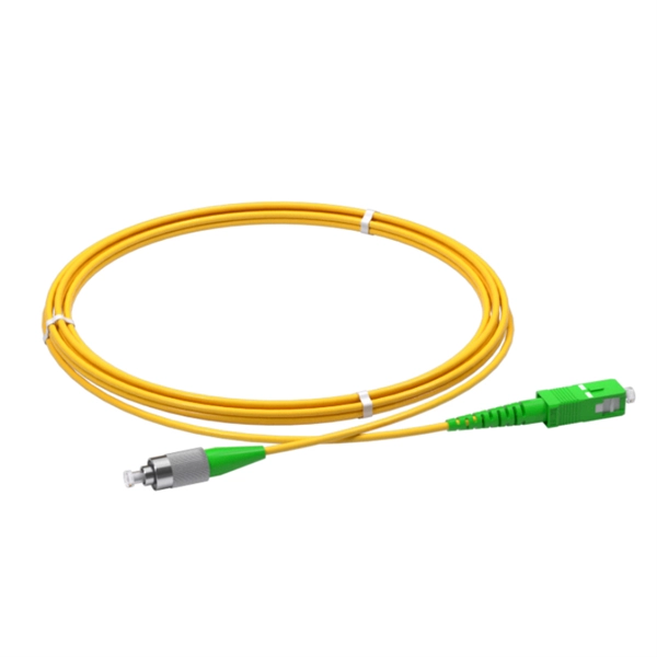
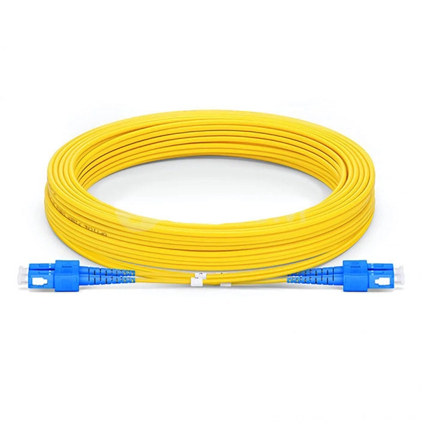
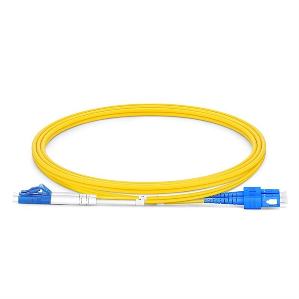
In this post, we'll walk you through practical tips, essential tools, common pitfalls, and the techniques that will help you get your fibre patch cable installations right the first time. Correct patch-cord installation is essential for maintaining low insertion loss, stable return loss, and long-term reliability in both indoor and outdoor fiber networks. Proper handling, routing, cleaning, bend-radius management, and connector alignment ensure that the optical link meets design. Proper connection of fiber optic cables is essential to harness these benefits fully, as even minor errors can lead to significant performance issues like signal loss. This guide addresses expert-certified best practices applied by professionals in the telecommunications, data. Yingda outlines the tools and materials needed to install fiber optic patch cords, as well as a complete step-by-step installation guide and important safety considerations to take. We will also tie this procedure back to the earlier discussion of multi-mode fiber types (OM1 to OM5) and connection. The Flex-Angle boot is designed to bend any angle or direction from straight to 90°. OMC flex angle boots for LC&SC fiber optic connectors are available on any single-mode or multimode patch cord. They are designed so the installer can pre-bend the boot into any direction or angle. Selecting the correct fibre patch lead is crucial for optimising signal performance and.
[PDF]
A fiber-optic splitter, also known as a, is based on a of an integrated waveguide power distribution device, similar to a The system uses an optical signal coupled to the branch distribution. The splitter is one of the most important in the link. It is an optical fiber tandem device with many input and output terminals, especially applicable to a passive optical network (,,,.
[PDF]
In conclusion, choosing the right fiber optic connectors is an important decision that can have a significant impact on the performance and reliability of your fiber optic network. By considering the various factors.
[PDF]

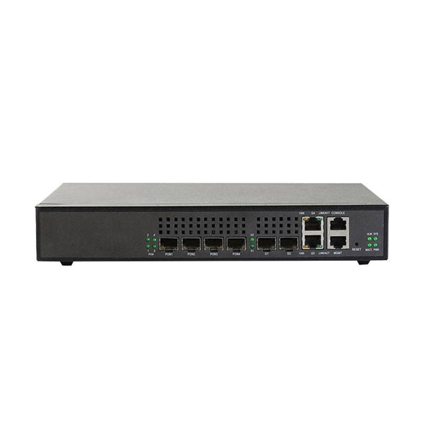
Configurations of 1x1 to n x m (e., 1x8 or 2x2) are available. The insertion loss of MM switches typically amounts to approximately 0. These switches can be delivered with any of the. Multimode fiber optic switches have emerged as a crucial component, enabling seamless connectivity and efficient data transmission. The MCSW Series Multicast Fiber Optical Switches enable simultaneous connection of one input to all outputs without loss. They support fully non-blocking, conflict-free switching of any number of optical inputs to any outputs, with complete configuration flexibility. The system is entirely passive. The Siemens Scalance X204-2 Multimode Switch requires a 24V UL Listed for Fire Application, Power Limited - Regulated Power Supply. Its Input Voltage is Regulated 24VDC and its Input Current is 265mA @ 24VDC. It is powered from the battery backed up local 24V power supply. Was this helpful? Does. For extremely precise measurement systems and sensor applications as well as for telecommunication applications LASER COMPONENTS offers fiber optical multimode (MM) switches with a fiber core diameter of 50 µm to 600 µm. There are switches are for all different kinds of requirements. Configurations. CONFIGURING THE SWITCH IN DESIGO CC/CERBERUS DMS. CYBERSECURITY DISCLAIMER.
[PDF]